Flow measuring device

a flow measurement and flow control technology, applied in measurement devices, volume/mass flow measurement, instruments, etc., can solve the problems of airflow stagnation, surface contamination of heating resistors by suspended particulates, and impaired response of thermal flow measuring devices, etc., to achieve accurate detection of airflow and restrict the adhesion of particulates

Active Publication Date: 2008-10-02
DENSO CORP
View PDF7 Cites 3 Cited by
  • Summary
  • Abstract
  • Description
  • Claims
  • Application Information

AI Technical Summary

Benefits of technology

[0017]In view of the foregoing and other problems, it is an object of the present invention to produce an airflow measuring device having a sensing portion, which is capable of accurately detecting airflow and restricted from adhesion of particulates.

Problems solved by technology

However, suspended particulates such as dust are contained in intake air of the internal combustion engine, and such suspended particulates may adhere to the surface of the heating resistor and the lead members.
As a result, an output characteristic such as response of the thermal flow measuring device may be impaired.
However, oil contained in suspended particulates may adhere to the heating resistor and remain, even low-boiling-point components of the oil is partially evaporated on the heating resistor.
Thus, the surface of the heating resistor may be contaminated by suspended particulates containing oil.
However, the airflow is added with a vertical component directed to the surface of the heating resistor, and consequently stagnation is apt to arise in the airflow.
However, airflow may become unstable due to the protection member, and consequently airflow cannot be accurately measured.
However, contamination of the heating resistor as an essential component may not be effectively suppressed.
However, suspended particulates, which contain oil, may not be removed and accumulate on the heating resistor.
As a result, the heat radiation characteristic changes, and the output characteristic such as response is impaired.
The above conventional structures are not sufficient to reduce adhesion.
Therefore, accuracy in output characteristic such as response of the detection of the airflow may be impaired.

Method used


Image

  • Flow measuring device
  • Flow measuring device
  • Flow measuring device

Examples


first embodiment

Operation of First Embodiment

[0053]Next, an operation of the airflow measuring device 1 is described.

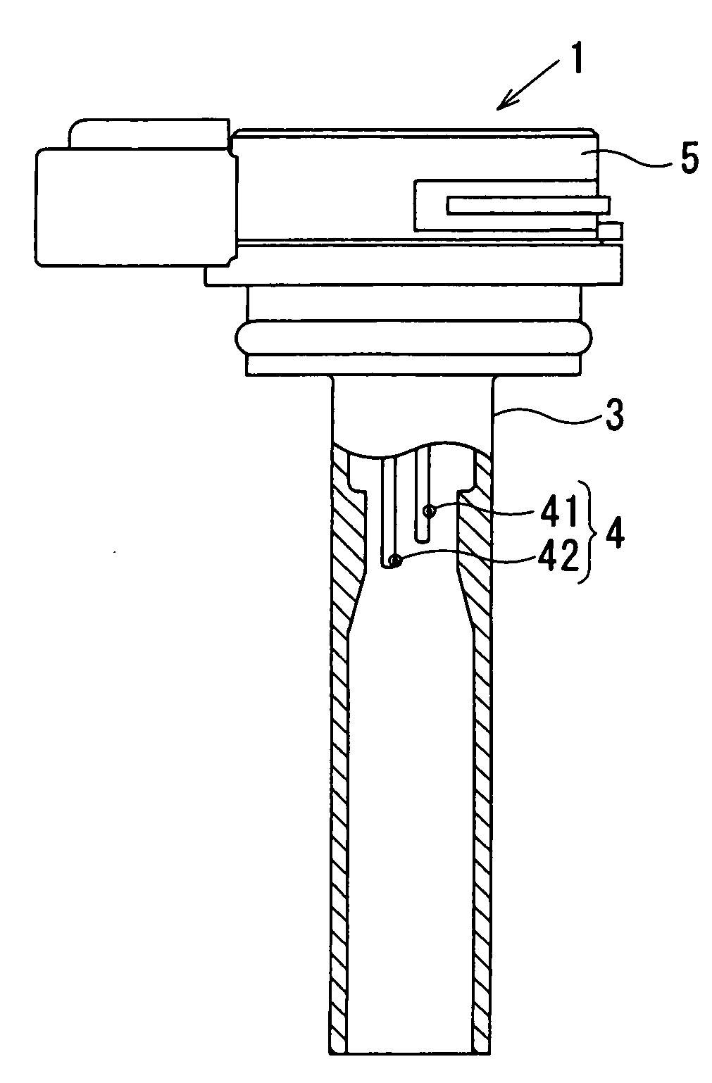
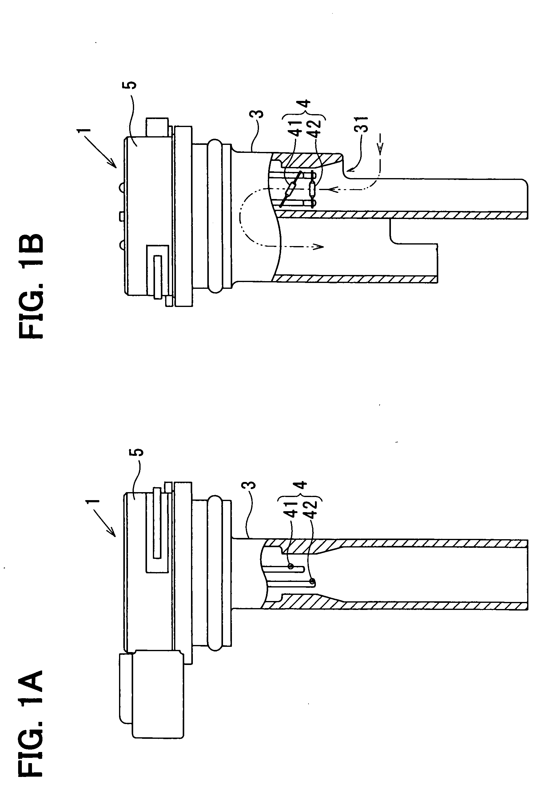
[0054]The engine is started, whereby mainstream of air is generated in the intake pipe 2. A part of the mainstream as the bypass flow is deflected at substantially 90° to pass through the bypass passage 6 of the sensor body 3. Suspended particulates contained in air flowing through the intake pipe 2 include relatively heavy and large particulates such as carbon particulates. Such relatively heavy and large particulates are applied with large inertia, thereby being apt to be separated by the inertia separation effect and adhered to the foundation wall of the sensor body 3.

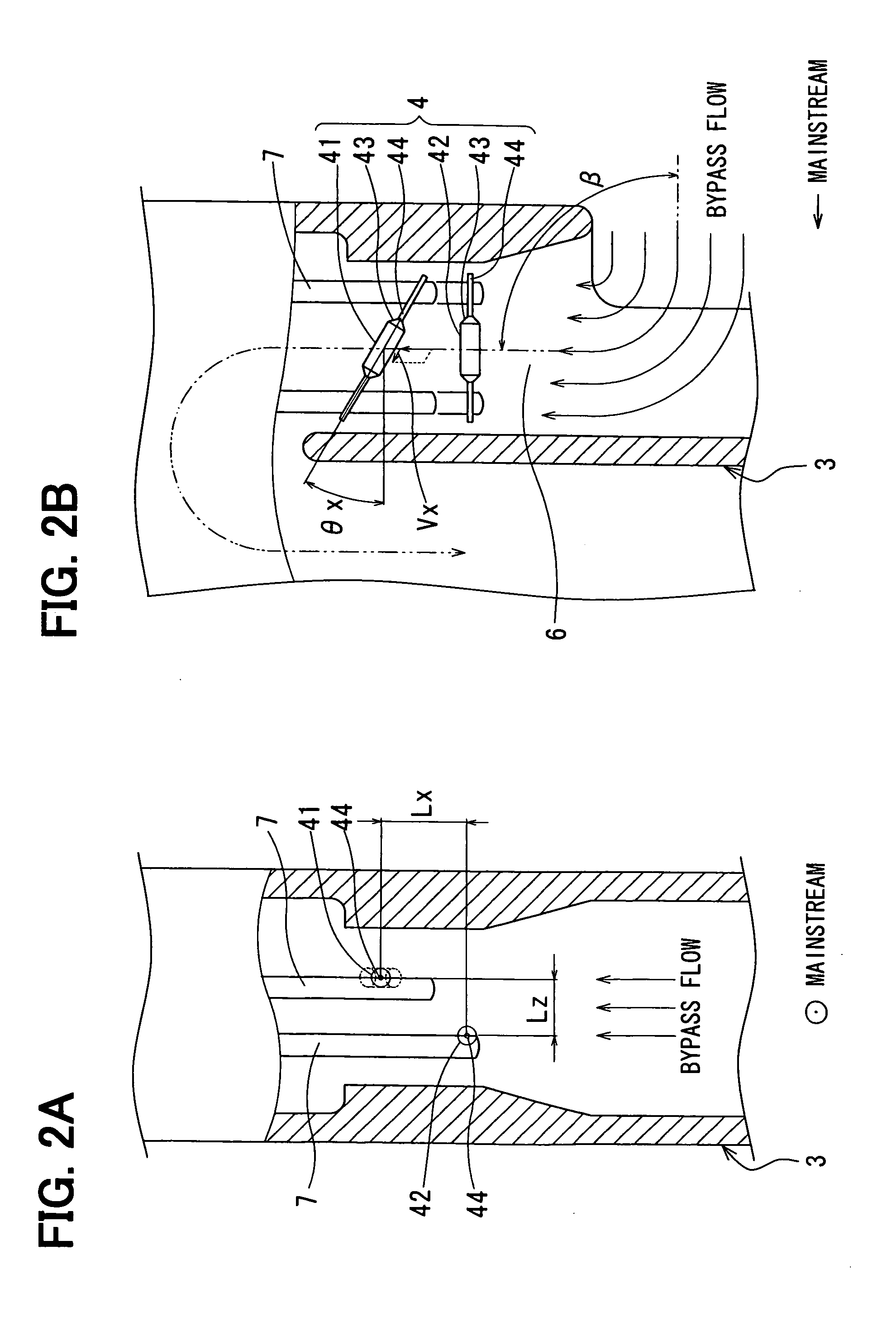
[0055]The mainstream is partially deflected at substantially 90° to form the bypass flow having the deflected flux therein defining a velocity distribution between the outer and inner streamlines. The streamlines defining the velocity distribution form the velocity component in the longitudinal direction of the heati...

embodiment

Effect of Embodiment

[0058]In the present embodiment, the airflow in the bypass passage is deflected at 90° with respect to the airflow in the main passage and bent perpendicularly to the direction, which is perpendicular to the airflow in the main passage. The sensing portion 4 includes the heating resistor 41 and the temperature-sensitive resistor 42, which are connected and supported by the pair of support members 7, which are erected in the bypass passage 6, via the pair of lead members 44. The heating resistor 41 and the temperature-sensitive resistor 42 are energized via the support members 7. The energization is controlled on the basis of heat radiation of the heating resistor 41 such that the temperature difference between the heating resistor 41 and the temperature-sensitive resistor 42 is maintained at the predetermined controlled temperature Ts. The sensing portion 4 for measuring the airflow in the bypass passage 6 is inclined by the predetermined inclination angle ex wit...

second embodiment

[0064]In the present embodiment, as shown in FIGS. 7A, 7B, each support member 7 has an end surface with respect to the longitudinal direction thereof, and the end surface is inclined at a predetermined inclination angle with respect to the streamline of the bypass flow. It suffices that at least one of the support member 7 has the inclined end surface as a slope. In the present structure, the end surface is capable of developing a boundary layer thereon to reduce stagnation, thereby suppressing adhesion of suspended particulates. Therefore, the boundary layer developed along each end surface of the support member 7 is also effective to reduce adhesion of suspended particulates in the connecting portion, in which the support member 7 is connected with the lead member 44 by, for example, welding. Further, adhesion of suspended particulates can be reduced on the surface along the longitudinal direction of each support member 7, similarly to the first embodiment.

[0065]Here, the predete...


PUM


Abstract

An airflow measuring device includes a sensing portion provided in a bypass passage, which perpendicularly deflects part of air from a main passage to therethrough bypass the part of air. The sensing portion includes a heating resistor energized and dissipate heat to airflow. The sensing portion is configured to measure airflow in the bypass passage based on the heat radiation. The sensing portion further includes a pair of support members erected in the bypass passage to support the heating resistor. The heating resistor of the sensing portion is inclined at a first inclination angle with respect to a direction, which is perpendicular to a flow direction of air in the bypass passage. The heating resistor is inclined toward downstream at an outer streamline of the airflow in the bypass passage.

Description

CROSS REFERENCE TO RELATED APPLICATIONS[0001]This application is based on and incorporates herein by reference Japanese Patent Application No. 2007-88604 filed on Mar. 29, 2007.FIELD OF THE INVENTION[0002]The present invention relates to a flow measuring device.BACKGROUND OF THE INVENTION[0003]Conventionally, a thermal flow measuring device is employed for measuring intake airflow of an internal combustion engine of a vehicle. A thermal flow measuring device includes a heating resistor and measures airflow in accordance with heat radiation from the heating resistor to the airflow. The heating resistor is constructed by winding a metallic resistive element around a bobbin in a cylindrical shape, and connecting both ends of the resistive element to a pair of lead members. The metallic resistive element is, for example, a platinum thin wire having a large temperature coefficient of resistance. The heating element is coated with a protective film at the surface and an end portion.[0004]...

Claims


Application Information

Patent Timeline
Patent Type & Authority Applications(United States)
IPC IPC(8): G01F1/692
CPCG01F1/6842G01F5/00
Inventor KOHNO, YASUSHIBAN, TAKAO
Owner DENSO CORP
Why Eureka
Try Eureka