
Solar heating panel fabricated from multi-wall plastic sheets

a multi-wall, plastic sheet technology, applied in the field of solar panels, can solve the problems of not becoming popular, many people cannot afford such a system, and solar water heaters are not very popular, and achieve the effects of convenient handling, high efficiency, and light weigh

Inactive Publication Date: 2008-10-02
SCHAEFER GUENTER
View PDF16 Cites 19 Cited by
  • Summary
  • Abstract
  • Description
  • Claims
  • Application Information

AI Technical Summary

Benefits of technology

[0007]What is needed is a low-cost solar water heating panel, that is highly efficien

Problems solved by technology

Solar water heaters have been installed for many years, but have not become very popular because they require a quite large investment, which amortizes over a very long time.
Because of the high expenses involved, many people cannot afford such a system, as the return ratio involves excessive time, even when such a project is financed.
Since the present designs of the solar water heating panels require materials and equipment that is not readily available in many places worldwide, shipping makes these products even more expensive and out of reach for many people.
In particular, prior-art solar panel designs require a heavy frame surrounding flexible panel elements.

Method used


Image

  • Solar heating panel fabricated from multi-wall plastic sheets
  • Solar heating panel fabricated from multi-wall plastic sheets
  • Solar heating panel fabricated from multi-wall plastic sheets

Examples


second embodiment

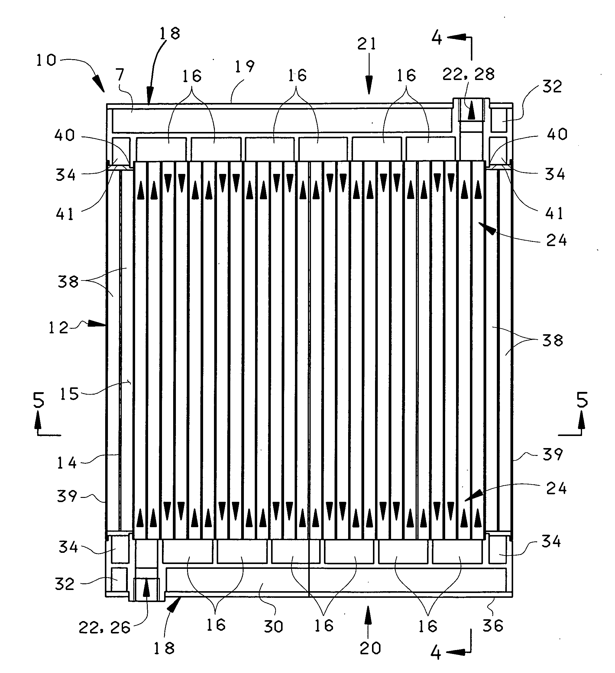
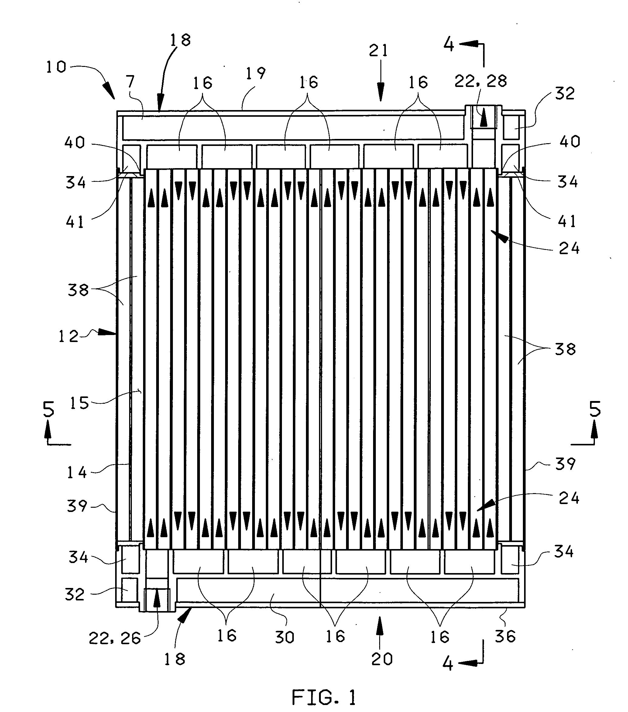
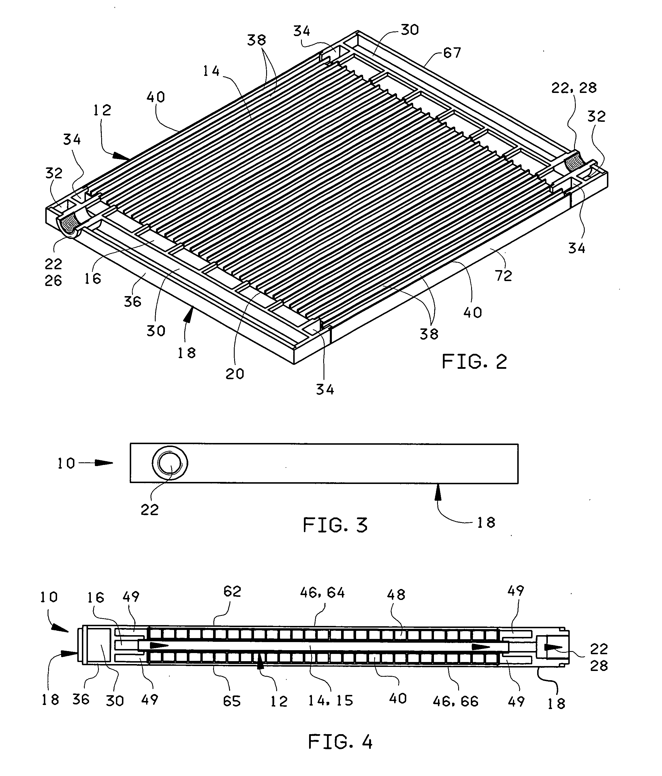
[0046]Alternate methods for fastening manifolds to multi-wall sheets will now be discussed, with reference being made to FIGS. 9-13. FIG. 9 is an isometric view of the solar panel 70, previously shown in FIG. 6, having the manifolds 72 and the side covers 52 adhesively attached to a pair of outer multi-wall sheets 46 and to a central multi-wall sheet 12 (shown in FIG. 6). FIGS. 10 and 11 show a solar panel 120, built in accordance with the invention, in which the manifolds 122 are each fastened to the multi-wall sheets 46, 12 by a number of screws 123. FIG. 10 is an isometric view of the solar panel 120, while

[0047]FIG. 11 is an isometric view of the multi-wall sheets 46, 12 therein. An array of clearance holes 124 is provided in the ends 126 of the outer multi-wall sheets 46, and a pair of brackets 128, extending within the outer channel 130 and having threaded holes 132 aligned with the clearance holes 124, are provided for engaging the screws 124. The screws 123 may additionally ...

third embodiment

[0053]FIGS. 19 and 20 show a solar panel 240 built in accordance with the invention, with FIG. 19 being an isometric view thereof, and with FIG. 20 being a cross-sectional plan view thereof. Arrows 241 show the directions in which a fluid 15 flows through the solar panel 240. The solar panel 240 includes a first manifold 242 having a port 244 at each end 246 of the manifold 242, and a second manifold 248 having no port 244. This configuration has an advantage of allowing pipes (not shown) carrying the fluid 15 into and away from the solar panel 240 to be attached at the same end 246 of the panel 240. Preferably, each of the manifolds, allowing the solar panel 240 the extend away from all plumbing connections. Both of the manifolds 242, 244 have an odd number of distributing cavities 248, so that the fluid 15 enters and leaves a central multi-walled sheet 250 from the same side 252 thereof.

[0054]It is understood that various features of one embodiment described herein may be readily ...


PUM


Abstract

A solar panel, through which a fluid is circulated, includes a transparent central panel, with a number of channels extending through the panel from one end to another. A manifold is attached to each end of the transparent central panel so that distributing chambers within the manifolds direct the fluid to move between adjacent channels within the central panel. The solar panel additionally includes a transparent support structure above the central panel and a lower support structure below the panel. Dark, opaque material below the central panel absorbs heat and warms the fluid.

Description

CROSS REFERENCE TO A RELATED APPLICATION[0001]This application claims the benefit of U.S. Provisional Application No. 60 / 920,093, filed Mar. 26, 2007.FEDERALLY SPONSORED RESEARCH OR DEVELOPMENT[0002]Not ApplicableBACKGROUND OF THE INVENTION[0003]1. Field of the Invention[0004]This invention relates to solar panels, and, more particularly, to solar panels including multi-layer translucent plastic sheets, known as multi-wall sheets, having an array of tunnels formed in the direction of extrusion, through which a fluid flows to be heated by solar radiation.[0005]2. Summary of the Background Art[0006]Solar water heaters have been installed for many years, but have not become very popular because they require a quite large investment, which amortizes over a very long time. Because of the high expenses involved, many people cannot afford such a system, as the return ratio involves excessive time, even when such a project is financed. Since the present designs of the solar water heating pa...

Claims


Application Information

Patent Timeline
IPC IPC(8): F24J2/05F24J2/10F24S10/40F24S10/70F24S23/70
CPCF24J2/05F24J2/202F24J2/243F24J2/506Y02E10/44F24S80/525F24S10/502F24S10/73F24S10/40F24S80/56
Inventor SCHAEFER, GUENTER
Owner SCHAEFER GUENTER
Learn More