
Thermosiphon for laptop computer

a laptop computer and heat exchanger technology, applied in indirect heat exchangers, semiconductor/solid-state device details, lighting and heating apparatus, etc., can solve the problems of relatively high cost of fabrication and relatively low heat capacity of air, and achieve the effect of efficient dissipation of heat and easy formation

Inactive Publication Date: 2008-10-02
COOLIT SYSTEMS INC
View PDF10 Cites 22 Cited by
  • Summary
  • Abstract
  • Description
  • Claims
  • Application Information

AI Technical Summary

Benefits of technology

[0010]The invention provides an alternative design for a compact thermosiphon that can be manufactured from stock parts and efficiently dissipates heat. The condensing tubes can be extruded tubing cut to the desired lengths with the boiling chamber and fins being easily formed in an analogous continuous and inexpensive process. By disposing the condensing tubes at an inclined angle they can be cut from continuously formed tubing and the fins are easily formed to fill the minimal space between the condensing tubes and the planes of the top and bottom of the boiling chamber.

Problems solved by technology

Heat exchangers and heat sink assemblies have been used that apply natural or forced convection cooling methods to dissipate heat from electronic devices that are highly concentrated heat sources such as microprocessors and computer chips; however, air has a relatively low heat capacity.
The cost of fabrication is relatively high when the thermosiphon is fabricated from especially dedicated and unique components as distinguished from being fabricated from stock materials.

Method used


Image

  • Thermosiphon for laptop computer
  • Thermosiphon for laptop computer

Examples


Embodiment Construction

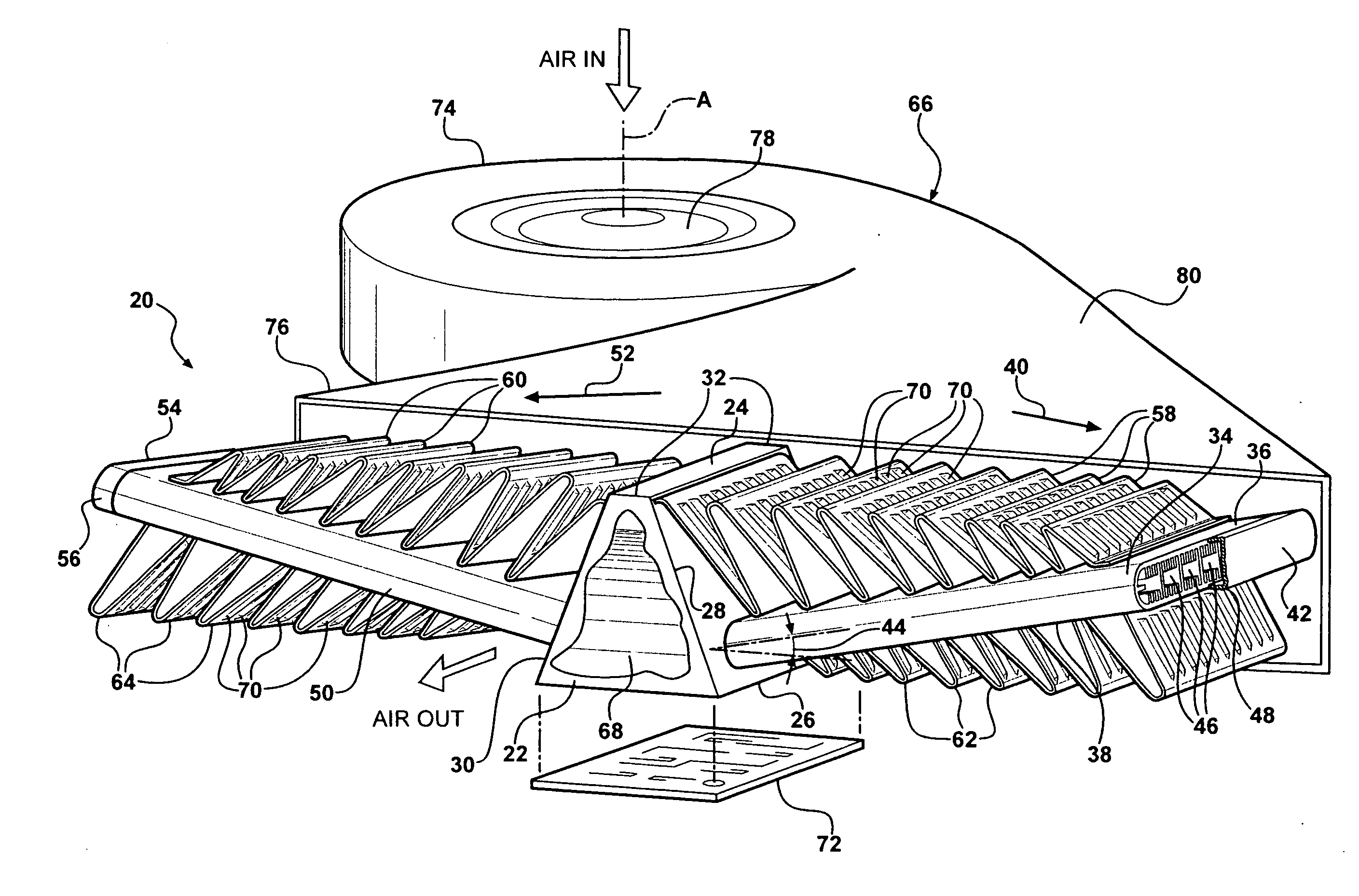
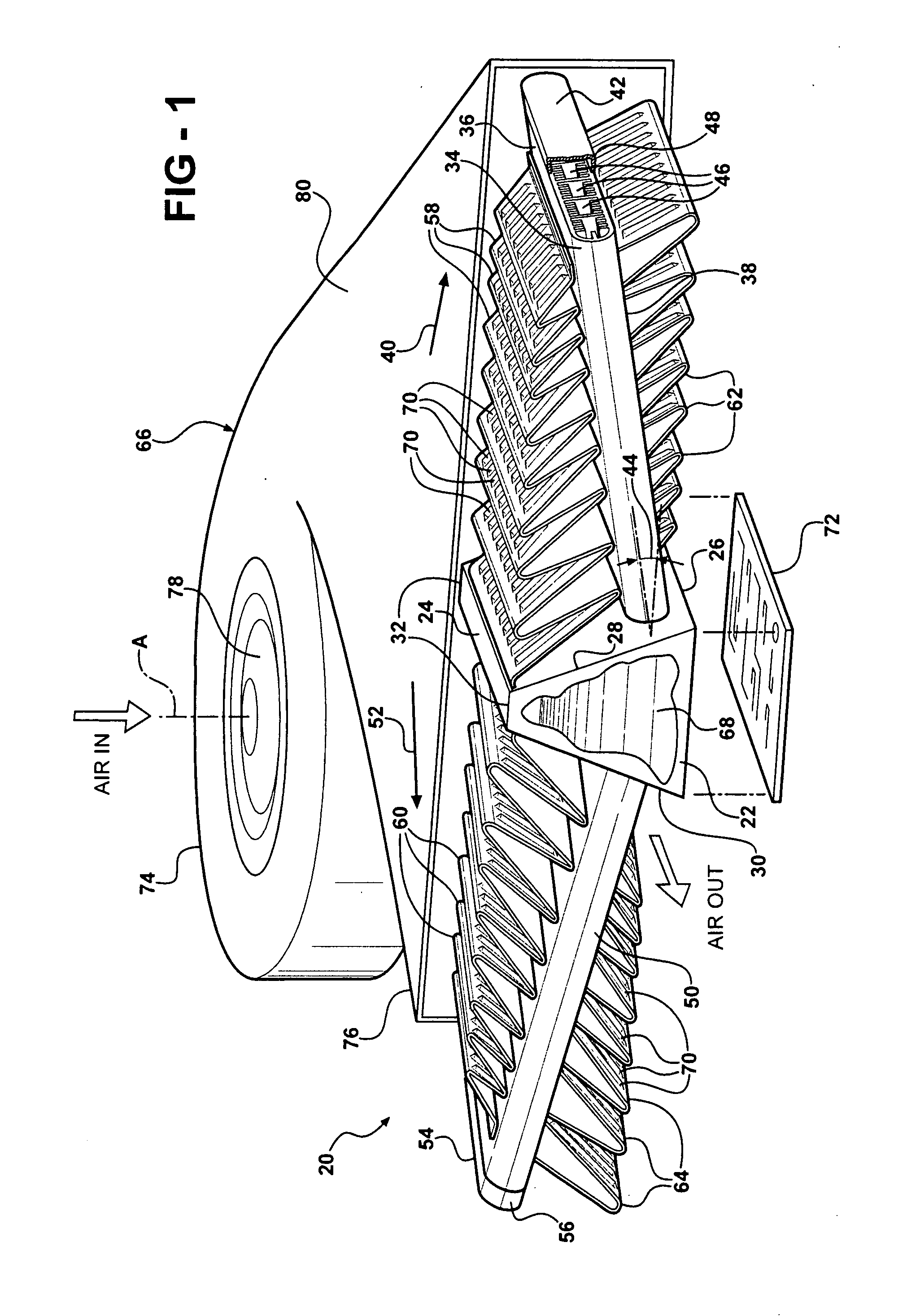
[0012]Referring to the FIGURE, wherein like numerals indicate corresponding parts throughout the several views, an assembly 20 is generally shown for cooling an electronic device.

[0013]The assembly 20 includes a boiling chamber 22 generally indicated having a top wall 24 and a bottom wall 26 parallel to the top wall 24 and a first side wall 28 and a second side wall 30 both extending inwardly from the bottom wall 26 to the top wall 24 and a pair of end walls 32 closing the chamber. A first condensing tube 34 attached to the first side wall 28 of the boiling chamber 22 has an elongated width presenting an upper surface 36 and a lower surface 38 and extends in a first direction 40 from the first side wall 28 to a first distal end 42 at an inclined angle 44 relative to the bottom wall 26 of the boiling chamber 22. The first condensing tube 34 includes a plurality of channels 46 across its width extending from the boiling chamber 22 to the first distal end 42 of the first condensing tub...


PUM


Abstract

A heat exchanger assembly is provided including a multi-function boiling chamber having a top wall and a bottom wall parallel to the top wall and a first side wall and a second side wall both extending inwardly from the bottom wall to the top wall and a pair of end walls closing the chamber. First and second condensing tubes attached to the first and second side walls, respectively, of the boiling chamber have an elongated width presenting an upper surface and a lower surface and extend in opposite respective directions to distal ends of the tubes at an inclined angle relative to the bottom wall of the boiling chamber. The condensing tubes include a plurality of channels across the width and extending from the boiling chamber to the distal end of the tube. A tank disposed at each of the distal ends of the condensing tubes is in fluid communication with the channels tubes. Upper air fins extending upwardly in a plane containing the top wall of the boiling chamber and lower air fins extending downwardly in a plane containing the bottom wall of the boiling chamber engage the respective upper and lower surfaces of both condensing tubes between the respective side walls of the boiling chamber and a position adjacent the respective distal ends of the condensing tubes.

Description

BACKGROUND OF THE INVENTION[0001]1. Field of the Invention[0002]This invention relates to a heat exchanger assembly for cooling an electronic device.[0003]2. Description of the Prior Art[0004]The operating speed of computers is constantly being improved to create faster computers. With this, comes an increase in heat generation and a need to effectively dissipate that heat.[0005]Heat exchangers and heat sink assemblies have been used that apply natural or forced convection cooling methods to dissipate heat from electronic devices that are highly concentrated heat sources such as microprocessors and computer chips; however, air has a relatively low heat capacity. Thus, liquid-cooled units called LCUs employing a cold plate in conjunction with high heat capacity fluids have been used to remove heat from these types of heat sources. Although, LCUs are satisfactory for moderate heat flux, increasing computing speeds have required more effective heat sink assemblies.[0006]Accordingly, th...

Claims


Application Information

Patent Timeline
Patent Type & Authority Applications(United States)
IPC IPC(8): F28D15/00H05K7/20
CPCF28D15/0233F28D15/0266F28F1/126H01L23/427H01L2924/0002H01L23/467H01L2924/00
Inventor BHATTI, MOHINDER SINGHREYZIN, ILYAJOSHI, SHRIKANT MUKUND
Owner COOLIT SYSTEMS INC
Features
  • Generate Ideas
  • Intellectual Property
  • Life Sciences
  • Materials
  • Tech Scout
  • Unparalleled Data Quality
  • Higher Quality Content
  • 60% Fewer Hallucinations
Learn More