Touch panel

a technology of touch panel and bending section, which is applied in the field of touch panel, can solve the problems of cracks, impaired conductive properties of films, and unavoidable complex structure of two touch panel panels, and achieve the effects of eliminating the risk of short circuit occurring at the bending section, faithful reproduction, and high quality imag

Inactive Publication Date: 2008-10-02
FUJITSU COMPONENENT LTD
View PDF16 Cites 30 Cited by
  • Summary
  • Abstract
  • Description
  • Claims
  • Application Information

AI Technical Summary

Benefits of technology

[0016]In the touch panel as described above, it is also possible to form an insulating layer in the bending section. With such construction, the risk of short circuit occurring at the bending section can be eliminated.
[0017]In the touch panel as described above, a multiplicity of dot spacers which have narrower separation than a space between dot spacers formed in the two operating regions can be formed in the bending section. With such construction, uniformity of gap between a pair of opposing conductive films can be maintained.
[0018]In the touch panel as described above, a color tone correction film can be formed for correcting the blue color of the conductive polymer material. With such color tone correction film, the color of the liquid crystal display or the like can be faithfully reproduced and a high quality image can be thereby obtained.
[0019]In the touch panel as described above, the color tone correction film can be a hard coat layer containing yellow pigment as a color correcting component. With such hard coat layer, the blue color of the conductive polymer material can be effectively weakened.
[0020]In the touch panel as described above, an external circuit arrangement can be electrically connected to the fixation side conductive film and the operation side conductive film at one location via a prescribed wiring pattern. Since an external circuit arrangement such as FPC is connected at one location, the construction of the touch panel can be simplified.
[0021]The touch panel as described above can be applied to a folding type information apparatus having two folding liquid crystal regions such that the two input operation regions are adhered to the two liquid crystal regions. The touch panel can also be applied to an electronic paper that displays an image by application of a magnetic field or an electric field. Since the touch panel can be formed on two liquid crystal regions of a folding type information apparatus or on an electronic paper, operability of information input to the information apparatus can be improved, and the range of application of the touch panel can be expanded.

Problems solved by technology

Thus, there is a problem that two sets of flexible circuit bodies 71, 81 for the two touch panels are required, and structure of the two touch panels becomes unavoidably complicated.
Since the ITO film is rigid and fragile like a thin glass plate, there is a problem that, when the ITO film is bent with a small radius of curvature R, cracks are produced and the conductive property of the film is impaired.
That is, there is a problem that the ITO film is damaged due to the stress exerted on the bent portion of the ITO film.

Method used


Image

  • Touch panel
  • Touch panel
  • Touch panel

Examples


Embodiment Construction

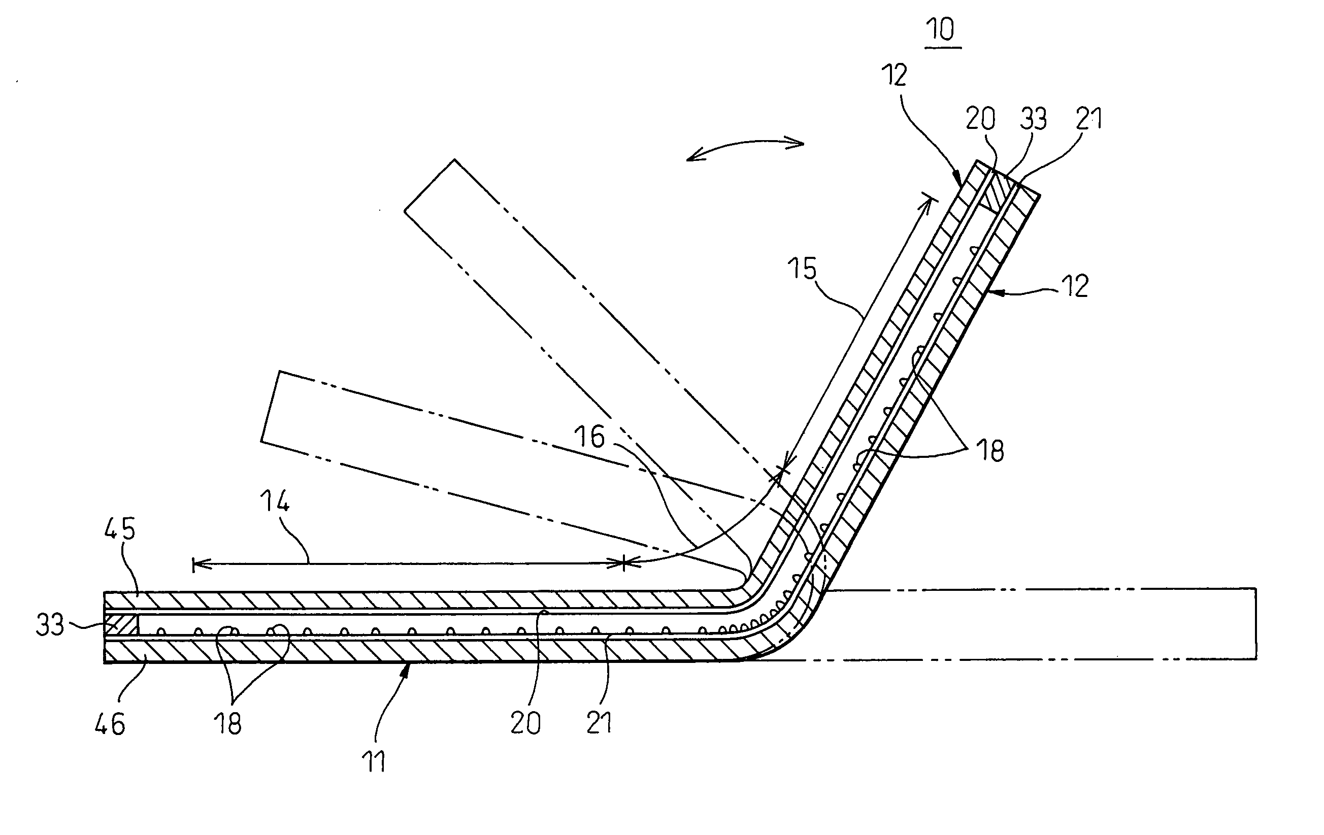
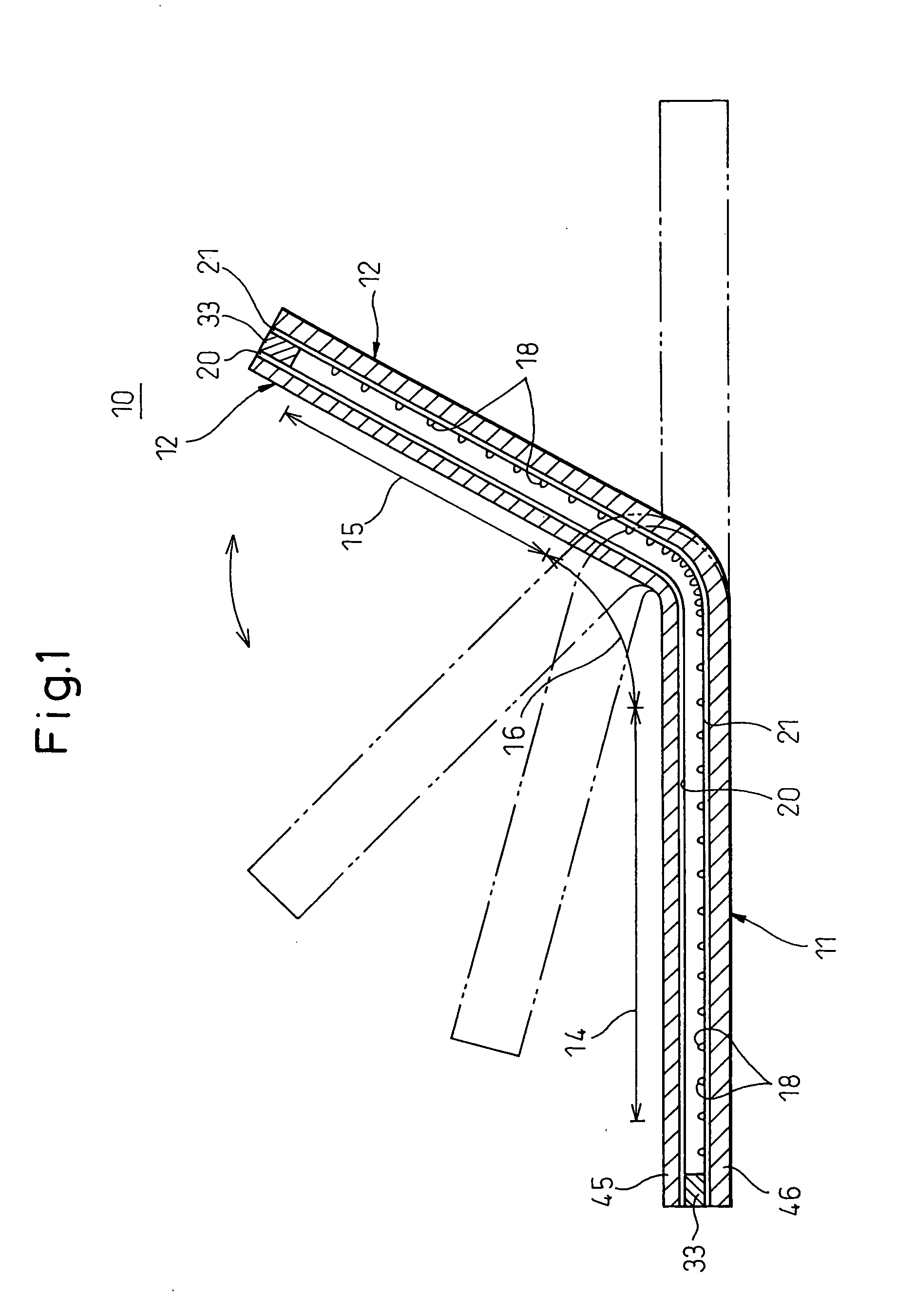
[0040]Now, the present invention will be described in detail with reference to drawings showing specific examples of embodiments thereof. FIG. 1 is a view of a touch panel according to an embodiment of the invention.

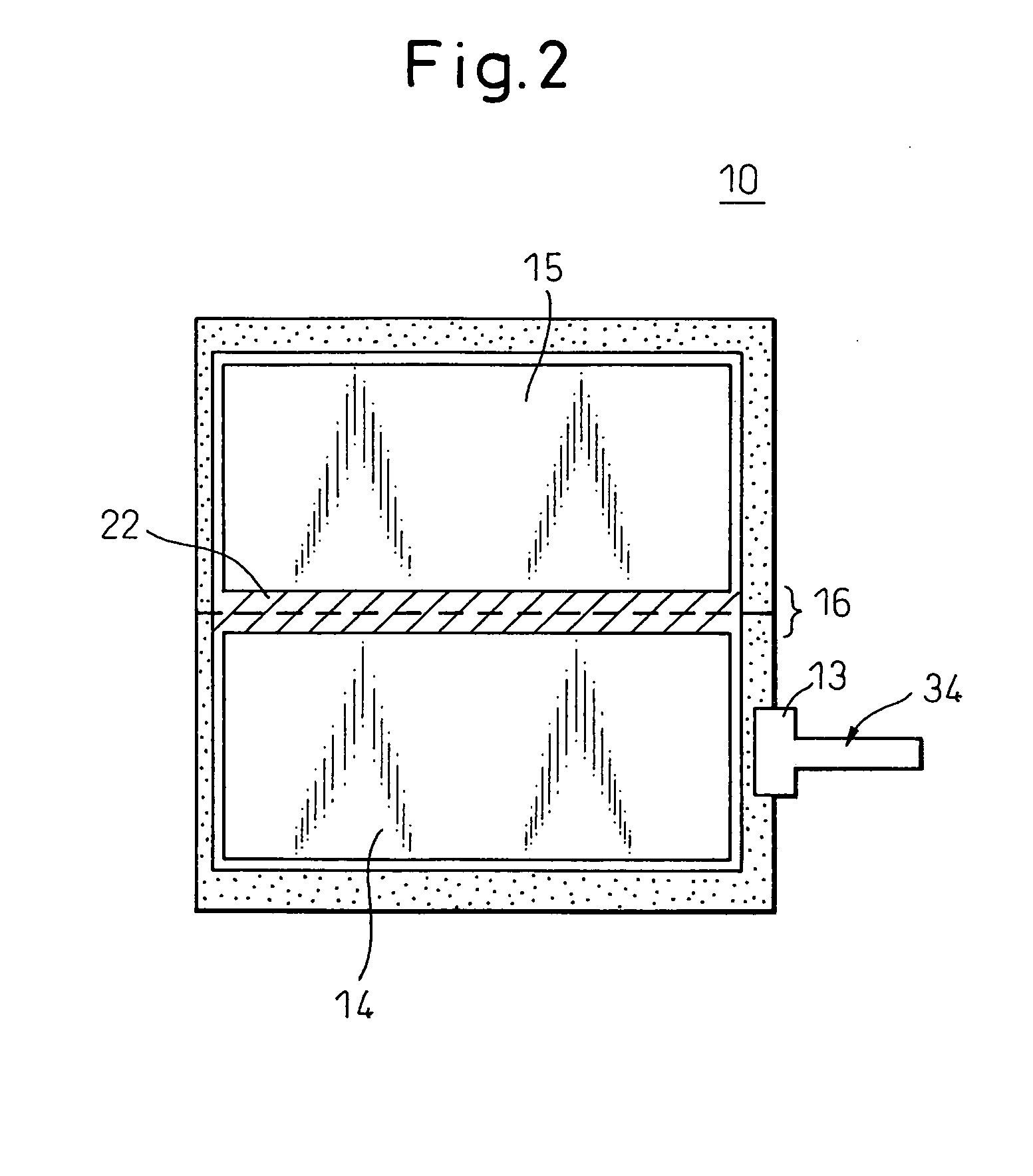
[0041]As shown in FIG. 1, a resistive film type touch panel 10 of this embodiment comprises a fixation side substrate (film) 11 that is a lower substrate to be adhered to a liquid crystal screen, an operation side substrate (film) 12 that is a substrate to be pressed by a finger, a pen, or the like, disposed opposite to the fixation side substrate 11, and a FPC connector 13 that electrically interconnects the two substrates 11, 12 to the main body of the apparatus. The touch panel 10 is applied to a folding type information apparatus 50 (FIG. 4) having two liquid crystal screen regions, and is integrally formed in one sheet having two input operation regions 14, 15 and a bending region (bending section) 16 between the two input operation regions 14, 15. Thus, one operati...


PUM


Abstract

A touch panel including a fixation side substrate and an operation side substrate disposed in opposition and adhered to each other, having a fixation side conductive film and an operation side conductive film respectively formed on opposing faces of the fixation side substrate and the operation side substrate, and being capable of detecting any contact point on the fixation side conductive film and the operation side conductive film as a 2-dimensional coordinate, wherein a bending section is formed between one end and the other end thereof, and wherein two input operation regions are defined and formed on both sides of the bending section.

Description

CROSS REFERENCE TO RELATED APPLICATIONS[0001]The present application claims the benefit of priority based on Japanese Patent Application No. 2007-093493, filed on Mar. 30, 2007, Japanese Patent Application No. 2007-164246, filed on Jun. 21, 2007, and Japanese Patent Application No. 2007-306418, filed on Nov. 27, 2007, disclosure of which is incorporated herein in their entirety by reference.BACKGROUND OF THE INVENTION[0002]1. Field of the Invention[0003]The present invention relates to a touch panel having a fixation side substrate and an operation side substrate disposed in opposition and adhered to each other, and being capable of detecting any contact point as a 2-dimensional coordinate in input operation areas being inside of a frame.[0004]2. Description of the Related Art[0005]In recent years, the application of touch panels has become more and more widespread, and the touch panels have been increasingly mounted on portable information apparatuses. In a portable information app...

Claims


Application Information

Patent Timeline
Patent Type & Authority Applications(United States)
IPC IPC(8): G06F3/041
CPCG02F1/13338G06F3/0412G06F3/045
Inventor ENDO, MICHIKOYAMAMOTO, TAKASHI
Owner FUJITSU COMPONENENT LTD
Why Eureka
Try Eureka