One-way clutch

a one-way roller and clutch technology, applied in the direction of mechanical actuator clutches, mechanical springs, mechanical apparatus, etc., can solve the problems of unstable attitudes of coil springs, insufficient durability, and inability to use coil springs having a larger diameter than rollers, so as to stabilize the attitude of coil springs, stabilize the pressing force, and minimize the inclination of the roller abutment portion

Inactive Publication Date: 2008-10-02
NTN CORP
View PDF7 Cites 10 Cited by
  • Summary
  • Abstract
  • Description
  • Claims
  • Application Information

AI Technical Summary

Benefits of technology

[0007]The roller abutment portion of each of the coil springs may comprise a flat spiral, or may comprise a conical spiral. With the latter arrangement, it is possible to minimize the inclination of the roller abutment portion, thereby applying stable pressing force to the roller. The coil springs may have a circular cross-section, or a rectangular cross-section. The coil springs may be formed of wires having a circular cross-section or a rectangular cross-section.
[0008]The one-way clutch may further comprise a retainer mounted between the inner and outer rings and fixed to the outer ring, the retainer having pockets each receiving one of the rollers and spring-receiving recesses each communicating with one of the pockets and receiving the second end of one of the coil springs. With this arrangement, it is possible to further stabilize the attitudes of the coil springs.
[0009]By using coil springs for elastic members for pressing each roller toward the narrow portion of the wedge-shaped space, because the coil springs are free of stress concentration, it is possible to improve the durability of the one-way clutch.
[0010]By providing the radially outwardly extending spiral roller abutment portion at the end of each coil spring that faces the roller, even if this end of the coil spring is radially displaced, the roller abutment portion is kept in contact with the roller, so that it is possible to prevent the end of the coil spring from slipping along and separating from the cylindrical outer surface of the roller. This stabilizes the attitudes of the coil springs, thereby making it possible to stably press the rollers. That is, it is possible to reliably apply necessary pressing force to the rollers.

Problems solved by technology

Such elastic members tend to be broken due to stress concentration on the U-shaped bent portions thereof, and thus they are not sufficiently durable.
But due to limited installation space, it is impossible to use coil springs having a larger diameter than the rollers.
Also, because each coil spring is brought into contact with the roller at two points, the attitudes of the coil springs tend to be unstable.

Method used


Image

  • One-way clutch
  • One-way clutch
  • One-way clutch

Examples


Embodiment Construction

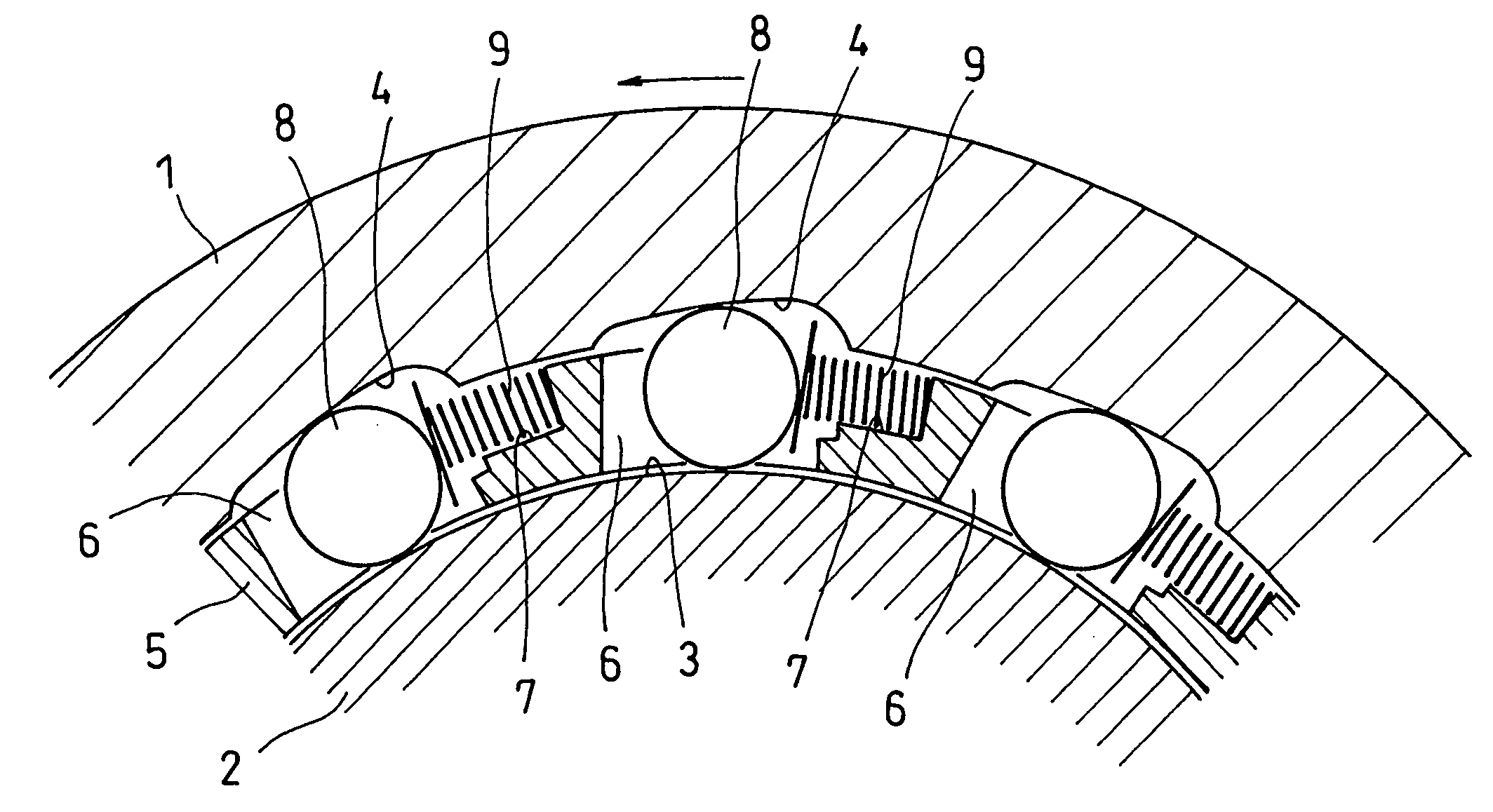
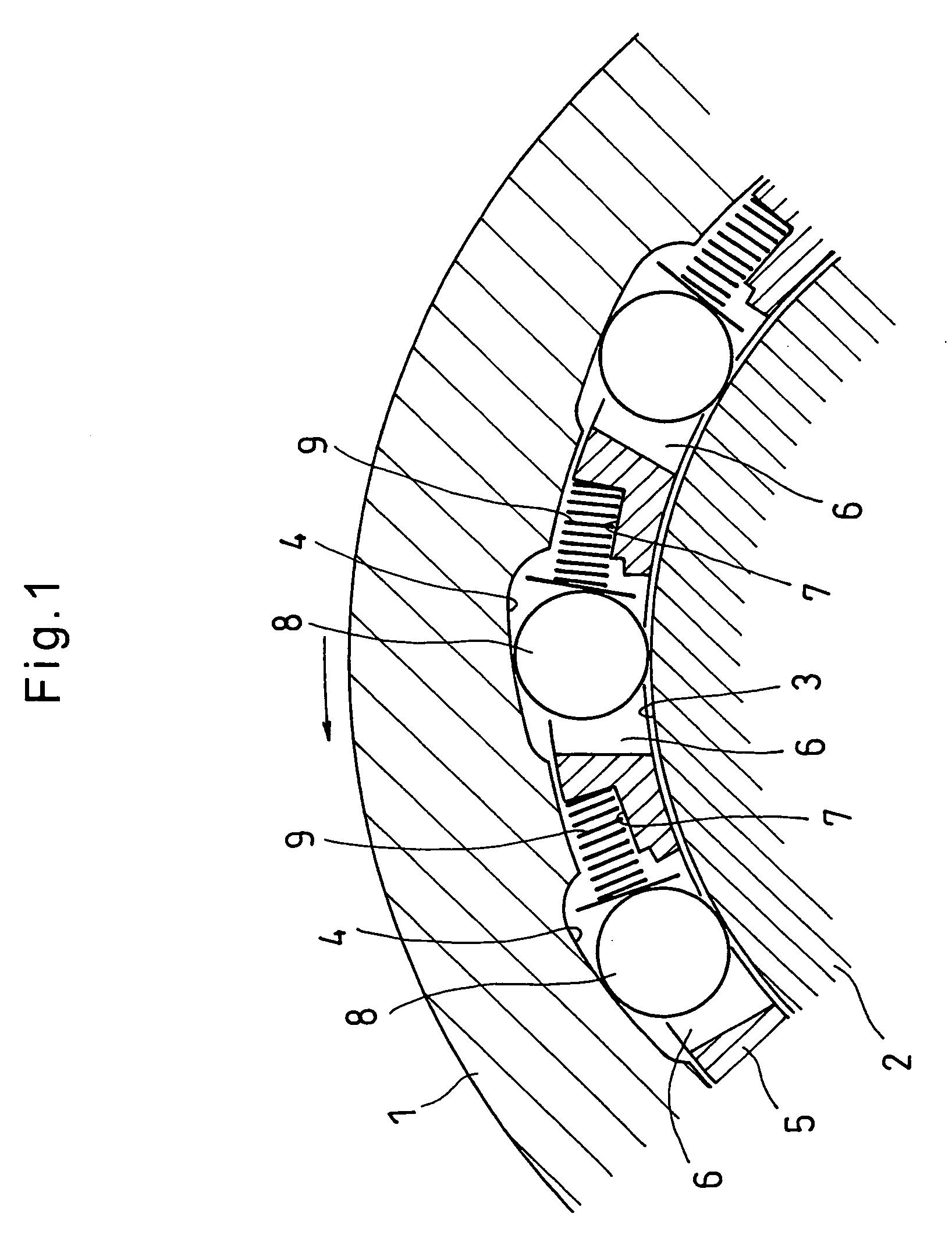
[0019]Now referring to the drawings, the embodiment of the present invention is described. As shown in FIG. 1, the one-way clutch of the embodiment includes an outer ring 1 and an inner ring 2 mounted inside the outer ring 1 and having a cylindrical outer surface 3.

[0020]On the inner periphery of the outer ring 1, a plurality of cam surfaces 4 are formed that are circumferentially spaced from each other. Between each cam surface 4 and the cylindrical surface 3 of the inner ring 2, a wedge-shaped space is defined of which the radial width gradually decreases from one circumferential end thereof toward the other circumferential end.

[0021]Between the outer ring 1 and the inner ring 2, a retainer 5 is mounted which is fixed to the outer ring 1. The retainer 5 is formed with pockets 6 each radially opposing one of the cam surfaces 4 of the outer ring 1. Each pocket 6 has two circumferential end walls that are located at the narrow and wide ends of the corresponding wedge-shaped space, re...


PUM


Abstract

A one-way roller clutch includes an outer ring, and an inner ring mounted inside the outer ring and having an outer cylindrical surface. The outer ring has on its inner periphery a plurality of cam surfaces each defining a wedge-shaped space in cooperation with the cylindrical surface of the inner ring. Rollers are each mounted between one of the cam surfaces and the cylindrical surface. Each roller is biased by a coil spring toward a narrow portion of the corresponding wedge-shaped space. Each coil spring has at its end facing the roller a radially outwardly extending spiral roller abutment portion. The roller abutment portion prevents the end of the coil spring from slipping along and separating from the roller, thus stabilizing the attitude of the coil spring.

Description

BACKGROUND OF THE INVENTION[0001]The present invention relates to a one-way roller clutch which is configured to transmit the rotation of its input member in one direction to its output member and stop transmission of the rotation of the input member when the output member begins to rotate at a higher speed than the input member.[0002]This type of one-way clutch is disclosed in JP Patent Publication 60-57020A, which includes an outer ring having on its inner periphery a plurality of cam surfaces circumferentially spaced from each other at equal intervals, and an inner ring having an outer cylindrical surface. A wedge-shaped space is defined between each cam surface and the cylindrical surface. A retainer is mounted between the inner and outer rings and fixed to the outer ring. The retainer is formed with pockets each opposing one of the cam surfaces and each receiving a roller and an elastic member biasing the roller toward the narrow end of the wedge-shaped space. With this arrange...

Claims


Application Information

Patent Timeline
Patent Type & Authority Applications(United States)
IPC IPC(8): F16D41/06
CPCF16D41/067F16D2041/0605
Inventor AKIYOSHI, KOJI
Owner NTN CORP
Why Eureka
Try Eureka