Rf Mems Switch With a Flexible and Free Switch Membrane

a technology flexible switch membrane, which is applied in the direction of relays, electronic switching, pulse techniques, etc., can solve the problems of dramatically reducing the lifetime of rf mems switch, subjected to high mechanical pressur

Inactive Publication Date: 2008-10-02
DELFMEMS SAS
View PDF5 Cites 15 Cited by
  • Summary
  • Abstract
  • Description
  • Claims
  • Application Information

AI Technical Summary

Benefits of technology

[0018]A further objective of the invention is to propose a novel RF MEMS switch that is less sensible to mechanical shocks or vibrations in comparison with the aforesaid RF MEMS switches having a stress-free and rigid switch beam.

Problems solved by technology

These switches are very sensible to temperature variations and to mechanical and / or thermal deformation of the substrate (first main drawback).
During actuation, when the anchored switch membrane is deformed under the force generated by the actuation means, the said membrane is subjected to high mechanical stress, which in turn dramatically decreases the lifetime of the RF MEMS switch (second main drawback).

Method used


Image

  • Rf Mems Switch With a Flexible and Free Switch Membrane
  • Rf Mems Switch With a Flexible and Free Switch Membrane
  • Rf Mems Switch With a Flexible and Free Switch Membrane

Examples


Embodiment Construction

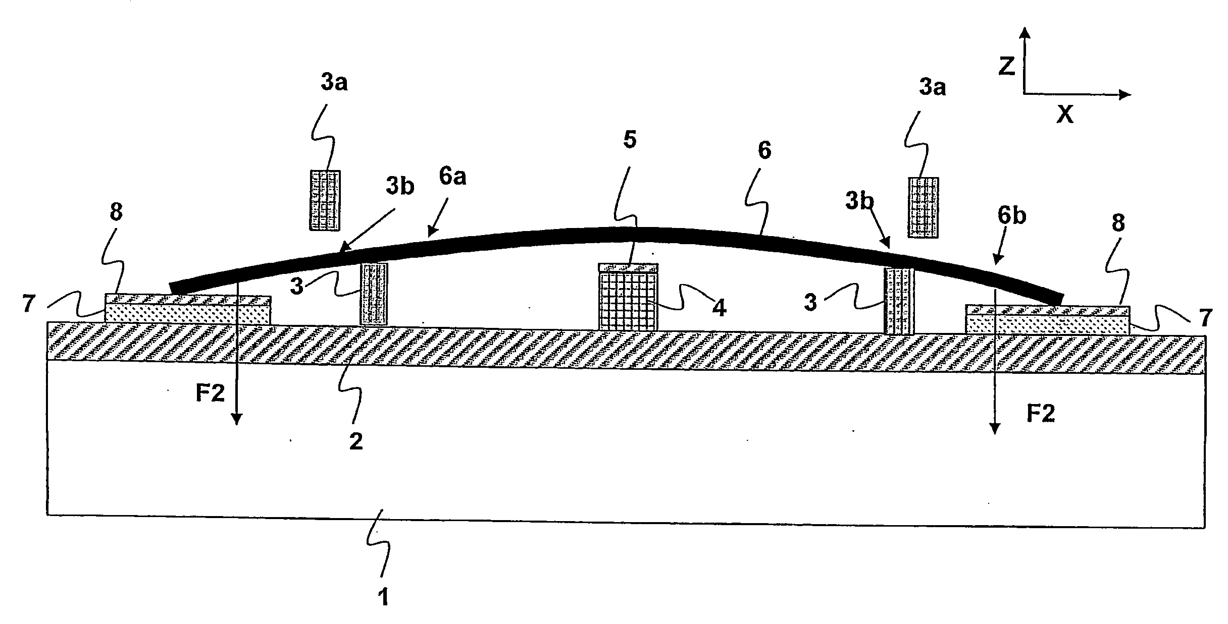
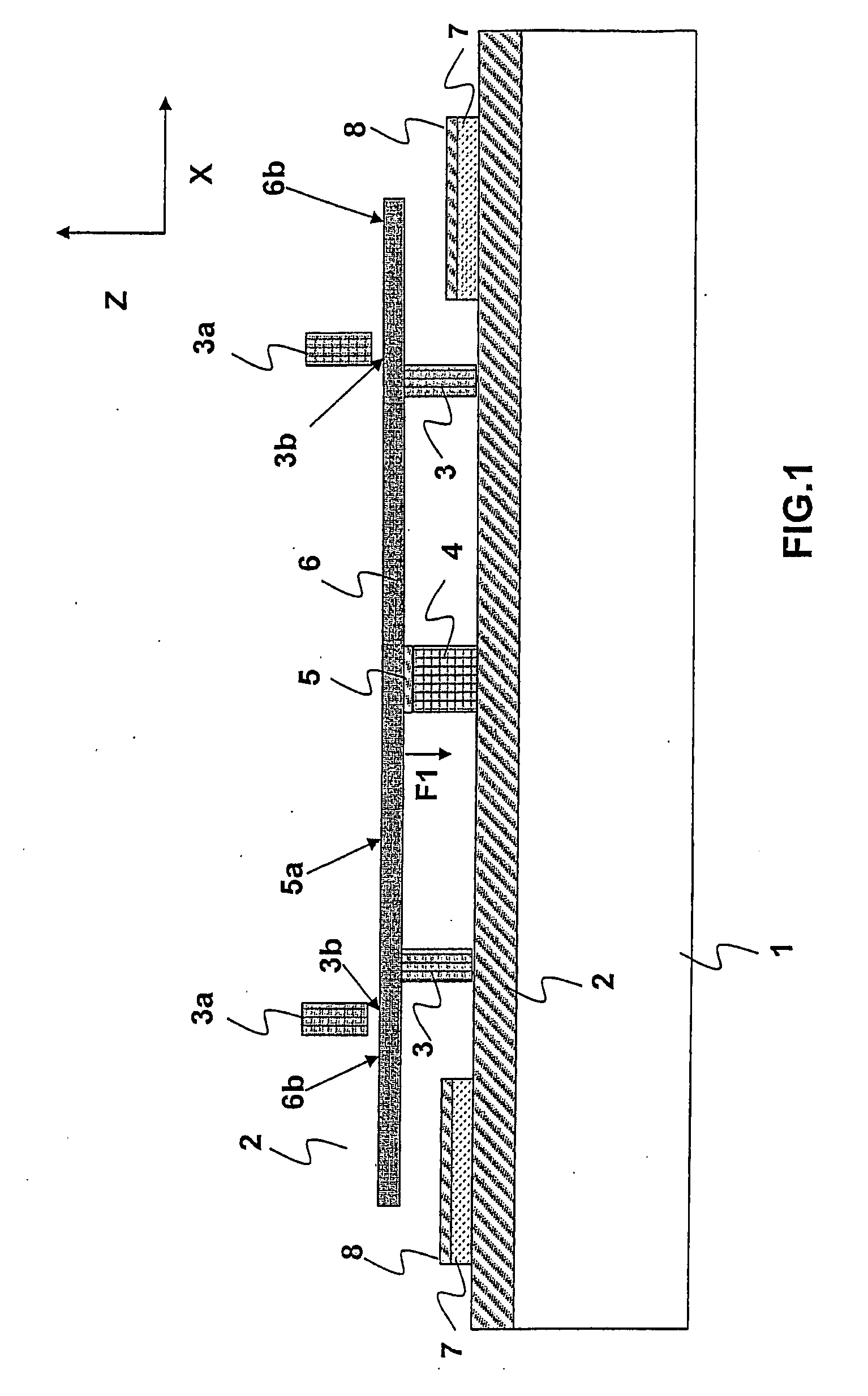
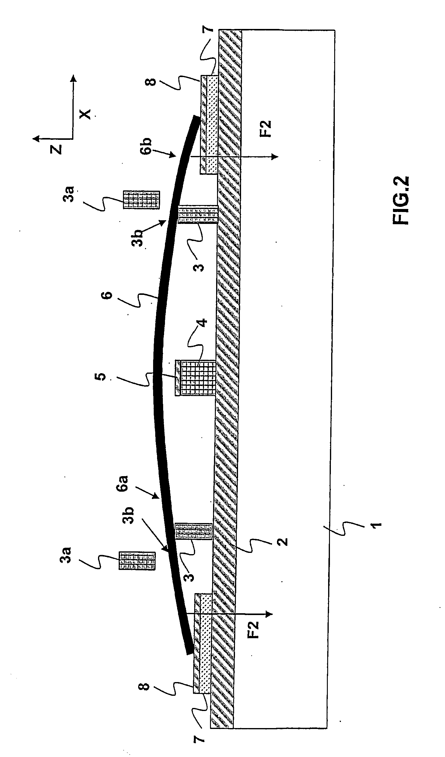
[0030]FIGS. 1 to 3 show a capacitive RF MEMS switch that is made according to preferred embodiment of the invention. For sake of clarity, it must however be underlined that the scope of the invention is not limited to a capacitive RF MEMS switch but encompasses also ohmic contact RF MEMS switches. The capacitive RF MEMS switch of FIGS. 1 to 3 has a novel structure that is now going to be detailed, and can be manufactured by using conventional surface micromachining technologies.

[0031]Referring to FIG. 1, the RF MEMS switch comprises a wafer 1 (for example made of silicium) forming the substrate of the switch. A thin dielectric layer 2 is deposited onto the surface of said wafer 1. On the dielectric layer 2, the switch comprises:[0032]two spaced-apart and parallel lateral supporting members 3, that extend in the transverse direction of FIG. 1 (see FIG. 3—direction Y).[0033]one central supporting member 4 that extends in a direction substantially parallel to the main direction of late...


PUM


Abstract

The RF MEMS switch comprising micromechanical switching means that are carried by a substrate (1) and that can be actuated between two positions: a first position (off-state/FIG. 1) and a second position (on-state), and actuation means for actuating the position of the switching means. The micromechanical switching means comprise a flexible membrane (6) which is freely supported by support means (3), which is bendable under the action of the actuation means (7), and which can freely slide relatively to the support means (3) during its bending movement.

Description

TECHNICAL FIELD[0001]The present invention relates to the technical field of Radio Frequency (RF) switches implemented by Micro Electromechanical Systems (MEMS).PRIOR ART[0002]Micro Electromechanical Systems (MEMS) switches are now widely used in Radio Frequency (RF) communication systems such as for example phased array antennas, phase shifters, switchable tuning components, etc.[0003]RF MEMS switches are essentially miniature devices that use a mechanical movement which is electrically actuated in order to achieve a short circuit or an open circuit in a RF transmission line. A RF MEMS switch thus essentially comprises two distinct means:[0004]micromechanical means that will be generally referred as “switching means” and that can be moved into two different positions: an off-position corresponding to the off-state of the switch, i.e. a state wherein the transmission line is opened and can not be used for transmitting a RF signal, and an on-position corresponding to the on-state of ...

Claims


Application Information

Patent Timeline
Patent Type & Authority Applications(United States)
IPC IPC(8): H03K17/975H01H59/00
CPCH01H1/0036H01H59/0009H01H2001/0063B81B5/00B81B2201/018H01H59/00
Inventor MILLET, OLIVIER
Owner DELFMEMS SAS
Why Eureka
Try Eureka