Fluid driven electric power generation system

a technology of electric power generation system and fluid pressure, which is applied in the direction of electric generator control, renewable energy generation, machines/engines, etc., can solve the problems of wind power generation system facing some difficulty in its stability, untapped potential, and wide use, so as to facilitate the initial starting of a traditional alternator and reduce the amount of fluid required. , the effect of increasing the fluid pressur

Active Publication Date: 2008-10-02
MDL ENTERPRISES
View PDF4 Cites 98 Cited by
  • Summary
  • Abstract
  • Description
  • Claims
  • Application Information

AI Technical Summary

Benefits of technology

[0024]In accordance with another feature of the present invention, power conditioning can be provided to generated power if necessary using conditioning circuits known in the art (e.g., filtering circuits). The size of the present system is scalable to meet delivery requirements.
[0025]In accordance with another feature of the present invention, the housing can be made of a tough light weight metal or a composite that will be able to withstand harsh environments while meeting the highest of standards.
[0026]In accordance with another feature of the present invention, a cowling can be located at the front of the alternator / fan with its point facing incoming fluid to cause the fluid to flow directly onto fan blades and not encounter a flat surface typically associated with the back of a alternator or center portion of a fan wherefrom blades extend. Pressure caused between the inner surface of the housing tubing and the cone / generator can force fluid directly onto the alternator fan blades and outward past the fan blades where the fluid can be exhausted from the second end of the housing.
[0027]In accordance with another feature of the present invention, a cupped fan blade can be included to enhance the effect of fluid pressure on the fan blades and ultimately as rotation of the alternator.
[0028]In accordance with another feature of the present invention, a clutching mechanism and / or mechanical breakaway can be provided to accommodate conditions where the wind speed exceeds rotational capabilities of the alternator and / or power output requirements / thresholds. Clutching can be provided in the form of a fan blade assembly designed with materials that can flex above threshold rotational speeds (RPMs) in order to prevent operation of the generator above damage causing thresholds, design parameters and generator capacity limits.
[0029]In accordance with another feature of the present invention, an electronic starting circuit can be provided in order to facilitate initial starting of a traditional alternator from periods when the alternator is idle (e.g., no rotation due to lack of fluid). The electronic starting system can provide an initial release of electrical energy to the windings in the generator to thereby reduce the amount of fluid required to spin-up or start rotation of the generator.

Problems solved by technology

Hydroelectric systems have also typically deployed as large industrial system and have not found wide use in the private sector.
Yet untapped potential exists with streams and shorelines near residential and commercial developments.
The wind power generation system faces some difficulty in its stability due to fluctuation in direction and speed of air.
It is unfortunate that such system must be so large, which in point of contention by many communities.

Method used


Image

  • Fluid driven electric power generation system
  • Fluid driven electric power generation system
  • Fluid driven electric power generation system

Examples


Embodiment Construction

[0054]The particular values and configurations discussed in these non-limiting examples can be varied and are cited merely to illustrate at least one embodiment and are not intended to limit the scope thereof.

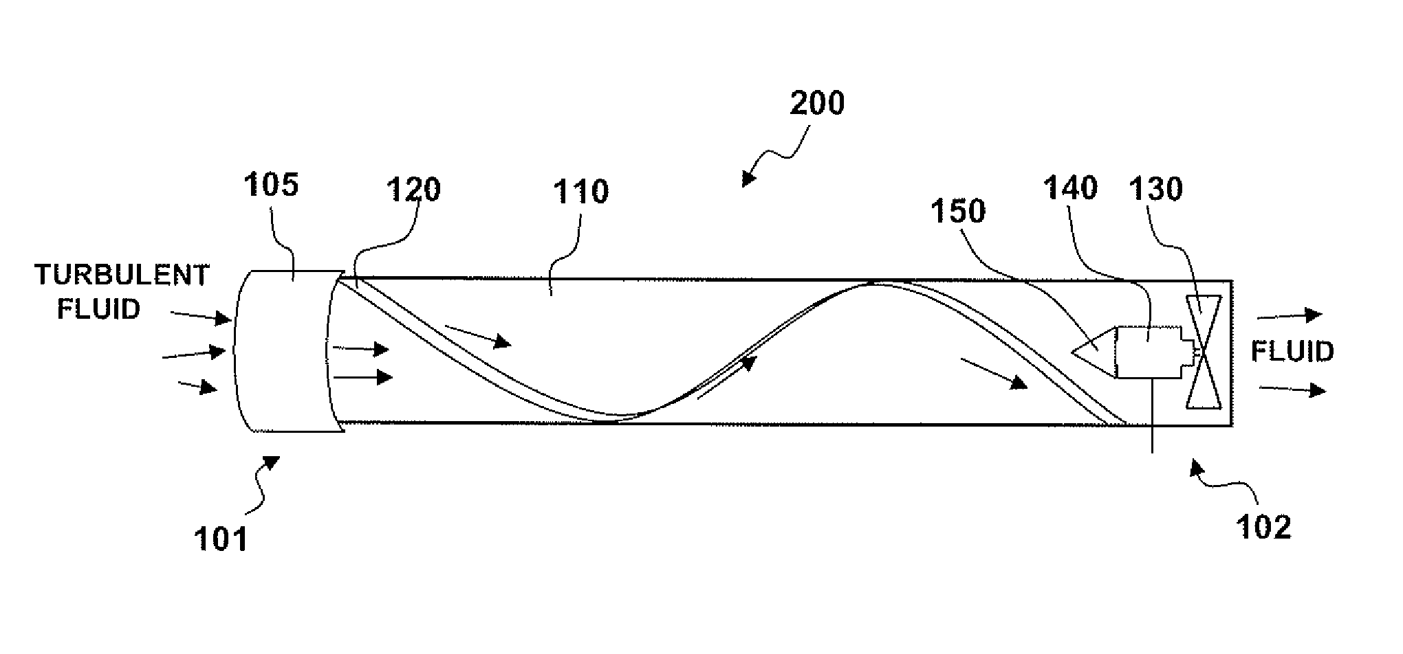
[0055]“Fan” or “fan blade” are commonly used in association with wind or airflow but as referred to herein should also be interpreted to include the meaning associated with “propeller” or “propeller blades” which are terms commonly used when referring to water flow as a fluid medium.

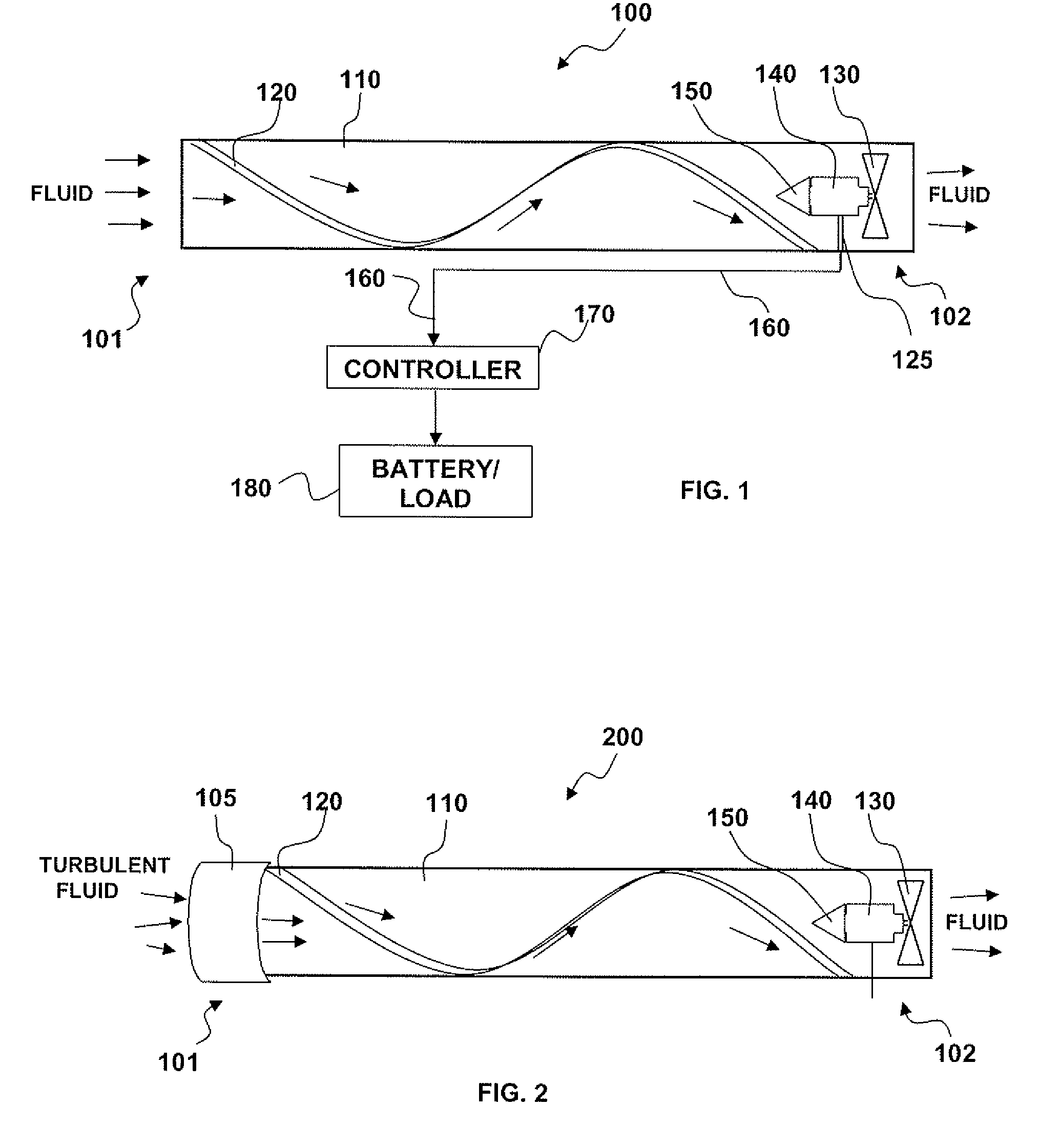
[0056]“Alternator” as used herein should also be interpreted to include “generator” as a means for producing electrical energy.

[0057]“Fluid” as used herein should be interpreted to include wind, airflow caused by forward motion of a vehicle, water flow caused by a stream or river, water flow as found within water distribution piping for commercial and private entities, and water flow as caused by the ocean.

[0058]FIG. 1 illustrates a block diagram of a wind driven electrical power generating system 1...


PUM


Abstract

A tubular housing includes at least one fixed helical vane formed onto the inner surfaces of the tubular housing in a spiral and adapted to direct fluid into a spiraled flow and focus fluid onto a fan blade assembly associated with an alternator system and located within the tubular housing before a system exhaust. A generator cone can be mounted near the center and front of the fan blade assembly facing fluid passing through the tubular housing. As fluid passes over the generator cone it experiences compression between the generator cone and housing resulting in increased pressure and velocity of the fluid, thereby increasing rotational speed of the generator blades and generator as the compressed, spiraled fluid passes through the blades and exits the tubular housing. The system can be used for fixed or mobile applications in water, wind and manually induced air flow.

Description

CONTINUATION AND PRIORITY DATA[0001]This application claims priority as a continuation-in-part patent application to non-provisional patent application Ser. No. 12 / 058,764, filed Mar. 31, 2008, entitled “WIND-DRIVEN ELECTRIC POWER GENERATION SYSTEM”, which also claims priority as a continuation to provisional patent application 60 / 921,331, filed Mar. 31, 2007 and to provisional patent application 60 / 953,206, filed Jul. 31, 2007, all herein incorporated by reference herein.TECHNICAL FIELD[0002]The present invention is generally related to renewable energy systems. More particularly, the present invention is related to fluid powered generator systems adapted for fixed and mobile electrical power generation systems and applications.BACKGROUND OF THE INVENTION[0003]Wind and stream or oceanographic water are forces of nature in the form of fluid that surround us and as a whole is barely being tapped for its energy generating potential. Wind is harnessed to sail ships, pump water, and cre...

Claims


Application Information

Patent Timeline
Patent Type & Authority Applications(United States)
IPC IPC(8): F03B13/00
CPCB60K6/485F03B13/10B60K2016/006B60W10/26B60W20/00B60W2510/244F03B11/02F03D1/04F03D3/04F03D9/002F05B2240/12F05B2240/13F05B2240/132F05B2240/941Y02B10/30Y02B10/70Y02E10/226Y02E10/72Y02E10/74Y02T10/6226B60K16/00F03D9/00F03D9/25F03D9/32F03D9/34F03D13/20Y02E10/20Y02E10/728Y02T10/62Y02T10/90
Inventor ORTIZ, LUIS M.BACA, ANTHONY MICHAELWICHERS, DONALD
Owner MDL ENTERPRISES
Why Eureka
Try Eureka