
Motor, rotor structure and magnetic machine

a rotor structure and motor technology, applied in the direction of dynamo-electric machines, magnetic circuit rotating parts, magnetic circuit shape/form/construction, etc., can solve the problems of difficult to secure the strength of the outer rotor, the need to cool the outer rotor, and the inability to achieve high efficiency, so as to achieve the effect of suppressing a magnetic short-circuit and improving magnetic efficiency

Inactive Publication Date: 2008-10-02
HONDA MOTOR CO LTD
View PDF20 Cites 30 Cited by
  • Summary
  • Abstract
  • Description
  • Claims
  • Application Information

AI Technical Summary

Benefits of technology

[0021]At this time, the phase of the magnetic pole of the first permanent magnet row and the phase of the magnetic pole of the second permanent magnet row of the first rotor are displaced from each other by a half of a predetermined pitch in the circumferential direction, and the phase of polarity of the first rotating magnetic field and the phase of the polarity of the second rotating magnetic field of the stator are displaced from each other by a half of the predetermined pitch in the circumferential direction. Therefore, the phase of the first induction magnetic pole and the phase of the second induction magnetic pole of the second rotor can be matched with each other. By this arrangement, not only the structure of the second rotor is simplified and strength is improved, but also supporting and assembling of the first, second induction magnetic poles in the second rotor are facilitated.
[0047]With the fourteenth feature, in the magnetic machine in which the induction magnetic-pole row is arranged between the first magnetic-pole row and the second magnetic-pole row, a distance between opposite ends in the linear direction of the induction magnetic poles of the induction magnetic-pole row is made smaller than at least one of a distance corresponding to an electric angle of 180° of the first magnetic-pole row and the distance corresponding to an electric angle of 180° of the second magnetic-pole row. Therefore, it is possible to suppress a magnetic short-circuit from being generated between the magnetic poles adjacent in the linear direction of the first magnetic-pole row or the second magnetic-pole row through the induction magnetic pole of the induction magnetic-pole row, thereby improving magnetic efficiency.

Problems solved by technology

However, the motor described in Japanese Patent Application Laid-open No. 11-341757 has a problem that a high efficiency cannot be obtained since the outer rotor is rotated by electromagnetic induction, and the motor functions not as a synchronous machine but as an induction machine.
Also, since the outer rotor is rotated by electromagnetic induction, an induction current generated at the coil of the outer rotor and an eddy current generated at the core of the outer rotor cause heat at the outer rotor, which results in a need to cool the outer rotor.
However, in the motor proposed in Japanese Patent Application No. 2006-217141, a phase of the first induction magnetic pole and a phase of the second induction magnetic pole supported by the outer rotor are displaced by a half pitch (an electric angle of 90°), which complicates a structure to support the first and second induction magnetic poles in the outer rotor, resulting in a problem that strength of the outer rotor becomes difficult to be secured.
Also, in the biaxial-output type motor disclosed in Japanese Patent No. 3427511, since fixing means such as a bolt is used as means to fix the induction magnetic pole to the rotor, the numbers of parts and assembling steps are increased accordingly, resulting in a problem of increased cost.
Particularly, when the induction magnetic pole is made of laminated steel plates, not only it is difficult to accurately machine a female screw therein, but also bolt-fastening strength cannot be sufficiently secured.
Therefore, magnetic efficiency is lowered, and performance of the rotating motor is not sufficiently exerted.

Method used


Image

  • Motor, rotor structure and magnetic machine
  • Motor, rotor structure and magnetic machine
  • Motor, rotor structure and magnetic machine

Examples


first embodiment

[0082]A first embodiment of the present invention will be described based on FIGS. 1 to 17G.

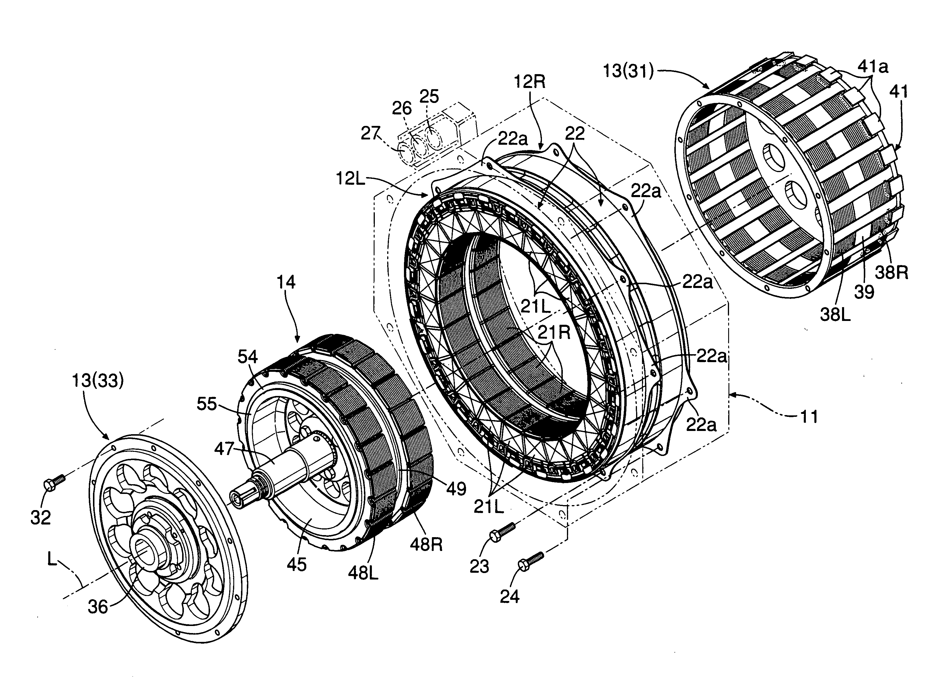
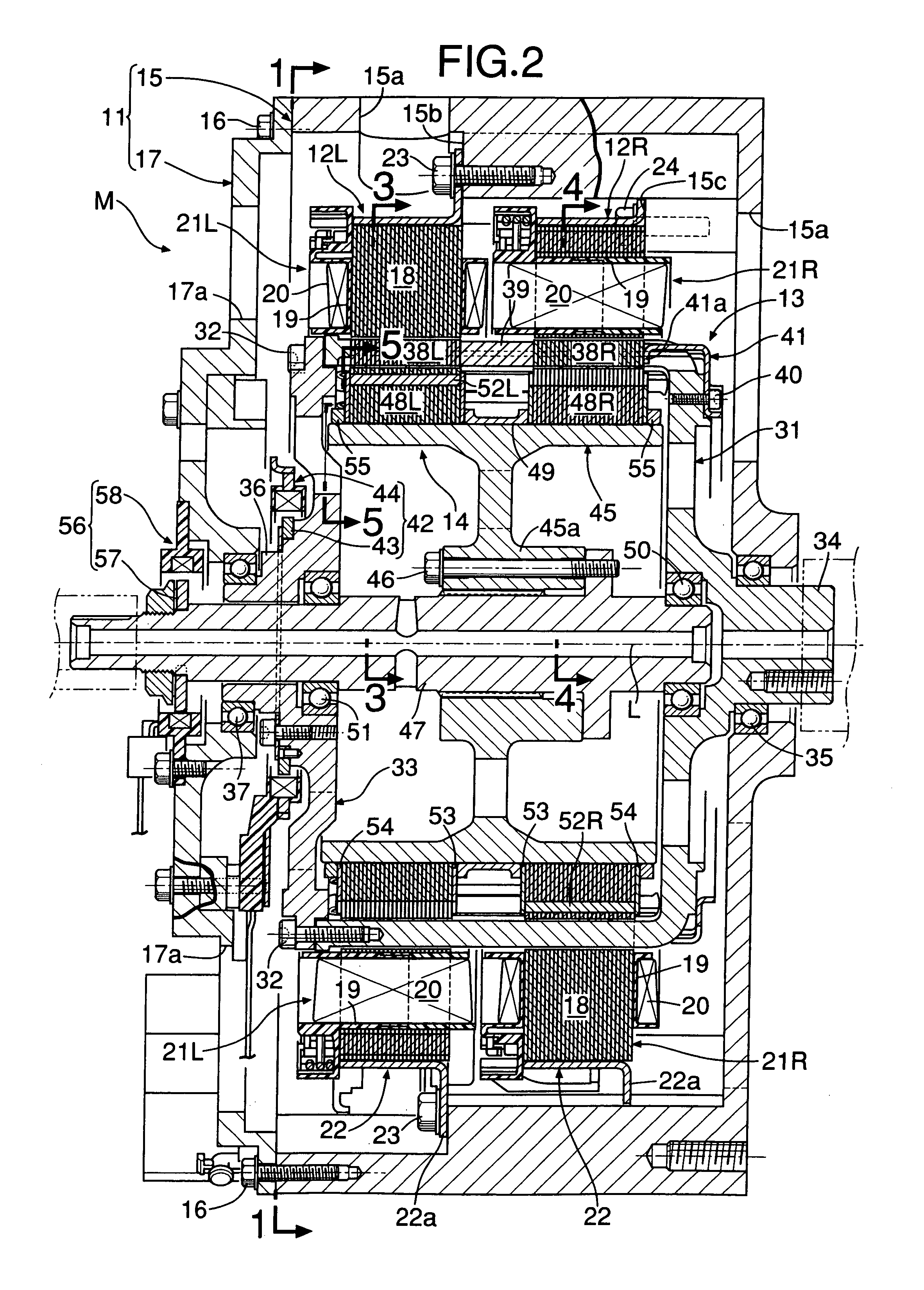
[0083]As shown in FIG. 7, a motor M of this embodiment comprises a casing 11 forming an octagonal cylindrical shape, which is short in a direction of an axis L, annular first and second stators 12L, 12R fixed to the inner circumference of the casing 11, a cylindrical outer rotor 13 accommodated within the first and second stators 12L, 12R and rotating around the axis L, and a cylindrical inner rotor 14 accommodated within the outer rotor 13 and rotating around the axis L. The outer rotor 13 and the inner rotor 14 are capable of relative rotation with respect to the fixed first and second stators 12L, 12R, and are capable of relative rotation with each other.

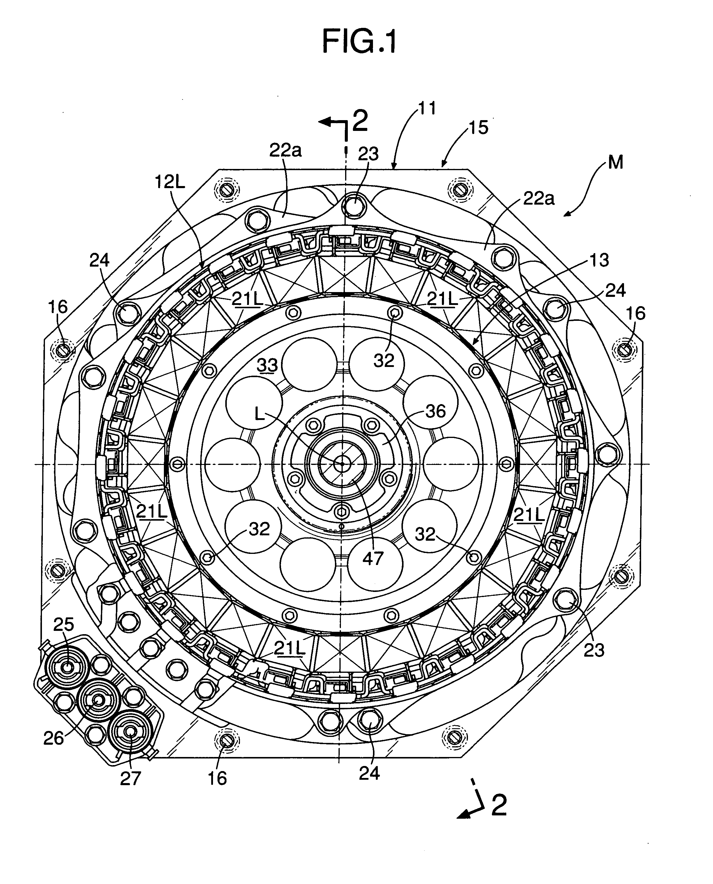
[0084]As obvious from FIGS. 1 and 2, the casing 11 has an octagonal bottomed cylindrical body portion 15 and an octagonal-plate-shaped lid portion 17 fixed to an opening of the body portion 15 with a plurality of bolts 16. A plurality of o...

second embodiment

[0138]Next, a second embodiment of the present invention will be described based on FIG. 18.

[0139]In the first embodiment, the shape of the recesses 38a, 39a of the first and second induction magnetic poles 38L, 38R and the spacer 39, as well as the shape of the projections 31b of the slits 31a in the rotor body 31 are square, but the same effects can be achieved also by a triangular shape as shown in FIG. 18A or an U-shape as shown in FIG. 18B.

[0140]Further, the first and second induction magnetic poles 38L, 38R can be reliably supported by reversing the positional relationship among the recesses 38a, 39a and the projections 31b, forming the projections on the side of the first and second induction magnetic poles 38L, 38R and the spacer 39, and forming the recesses on the side of the slits 31a. However, if the recesses 38a are formed on the side of the first and second induction magnetic poles 38L, 38R as in the embodiments, eddy loss and hysteresis loss can be reduced as compared ...

third embodiment

[0141]Next, a third embodiment of the present invention will be described based on FIG. 19 to FIG. 21.

[0142]In the third embodiment, grooves 39b extending in the circumferential direction are formed in the surface of the spacers 39 of the outer rotor 13, grooves 31d leading to the grooves 39b of the spacers 39 are formed in the outer circumferential face of the rotor body 31 of the outer rotor 13, and a ring 59 made of a weak magnetic body is fitted in the grooves 39b, 31d.

[0143]When the outer rotor 13 is rotated, a centrifugal force acts on the first and second induction magnetic poles 38L, 38R and the spacers 39, an intermediate portion of the rotor body 31 in the axis L direction is deformed to bulge. However, the intermediate portion of the rotor body 31 in the axis L direction is pressed by the ring 59, thereby preventing the deformation.


PUM


Abstract

A motor includes a stator having first and second armatures to form a rotating magnetic field, an inner rotor having first and second permanent magnets, and an outer rotor arranged between the stator and the inner rotor. The outer rotor has a rotor body which supports first and second induction magnetic poles such that they are embedded therein. A phase of the first induction magnetic pole is matched with a phase of the second induction magnetic pole. The first and second induction magnetic poles are assembled to the rotor body such that they are inserted into linear slits formed in the rotor body in the axis direction. Because the first and second induction magnetic poles are aligned in the axis direction, the outer rotor has a simple structure and an increased strength, and also support and assembling of the first and second induction magnetic poles in the outer rotor are facilitated.

Description

[0001]The Japanese priority application Nos. 2007-26422, 2007-26423, 2007-26424 and 2007-316189 upon which the present application is based are hereby incorporated in their entirety herein by reference.BACKGROUND OF THE INVENTION[0002]1. Field of the Invention[0003]The present invention relates to a motor comprising: annular stators arranged so as to surround an axis; a first rotor rotatable around the axis; and a second rotor arranged between the stator and the first rotor, and rotatable around the axis.[0004]Also, the present invention relates to a rotor structure comprising a rotor made of a soft magnetic body and rotating around the axis, and a plurality of induction magnetic poles made of a soft magnetic body and supported on the rotor at predetermined intervals in a circumferential direction.[0005]Further, the present invention relates to a magnetic machine comprising a first magnetic-pole row in which a plurality of magnetic poles are arranged in the circumferential direction...

Claims


Application Information

Patent Timeline
IPC IPC(8): H02K16/00H02K1/28
CPCH02K1/246H02K1/30H02K16/00H02K21/16H02K1/276H02K19/103H02K16/02
Inventor BANDO, MASASHIABE, NORIYUKIAKUTSU, SHIGEMITSUOYA, SATOYOSHI
Owner HONDA MOTOR CO LTD
Features
  • Generate Ideas
  • Intellectual Property
  • Life Sciences
  • Materials
  • Tech Scout
  • Unparalleled Data Quality
  • Higher Quality Content
  • 60% Fewer Hallucinations
Learn More