Actuator

a technology of actuators and actuators, applied in the field of actuators, can solve the problems of difficult to make the actuator thin and small, difficult to embody a flexible movement, and the actuator element to be caught in the pitch of the coil spring, etc., and achieves the effect of easy making a small size and large displacemen

Inactive Publication Date: 2008-10-02
SUMITOMO RIKO CO LTD
View PDF10 Cites 23 Cited by
  • Summary
  • Abstract
  • Description
  • Claims
  • Application Information

AI Technical Summary

Benefits of technology

[0009]The present invention has been developed in view of such circumstance, and it is an object of the present invention to provide an actuator which is easily made a small size and flexible, and has a large displacement.

Problems solved by technology

Hence, when extended, the actuator element can interfere with the coil spring to prevent the actuator from being displaced axially.
Hence, when contracted, the actuator element can interfere with the coil spring to cause, for example, the actuator element to be caught into the pitch of the coil spring.
Hence, it is difficult to make the actuator thin and small.
Furthermore, since the coil spring is rigid body, it has difficulty to embody a flexible movement.
Hence, with the actuator, it is difficult to arrange the extending direction in one direction.

Method used


Image

  • Actuator
  • Actuator
  • Actuator

Examples


first embodiment

Constitution of Actuator

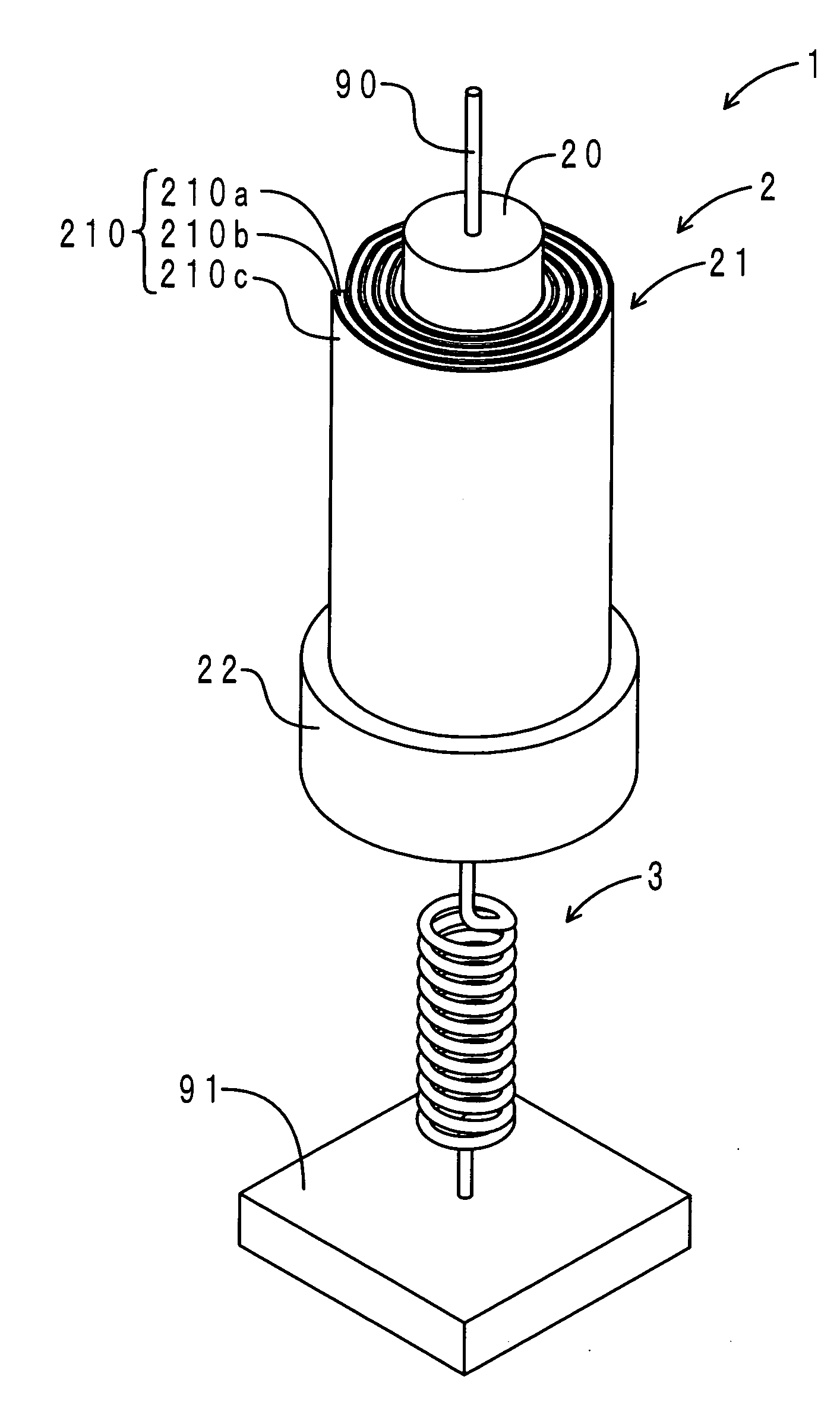
[0068]First, a constitution of the actuator of this embodiment is described below. FIG. 3 shows a perspective view of the actuator of this embodiment. FIG. 4 shows a perspective exploded view of the actuator element in the actuator. FIG. 5 shows an axially-perpendicular sectional view of the actuator. FIG. 6 shows an axially sectional view of the actuator. As shown in FIGS. 3 to 6, the actuator 1 of this embodiment has an actuator element 2 and a coil spring 3. The coil spring 3 is included in an elastic member (a load member) of the present invention.

[0069]The actuator element 2 has a core material 20, a spiral tube member 21 and a base member 22. The axially-perpendicular diameter of the actuator element 2 is about 5 mm. The core material 20 is made of an elastomer and is formed of a round rod shape. The upper-end of the core material 20 is fixed via a wire material 90 to an upper member (not shown).

[0070]The spiral tube member 21 is annularly installed aro...

second embodiment

[0085]The difference between the actuator of this embodiment and the actuator of the first embodiment is that in the actuator of this embodiment, a laminated tube member is arranged in place of the spiral tube member. Thus, only the difference will be explained here.

[0086]FIG. 8 shows an axially-perpendicular sectional view of the actuator of this embodiment. Further, the parts corresponding to those in FIG. 5 are indicated by the same symbols. As shown in FIG. 8, the actuator element 2 of the actuator 1 of this embodiment has laminated tube member 23. The laminated tube member 23 is annularly installed around the core material 20.

[0087]The laminated tube member 23 is formed such that three-layer dielectric films 230 and four-layer electrodes 231 are alternately laminated concentrically as if a tree ring. That is, a pair of the electrodes 231 is arranged on both the radial sides of any dielectric film 230.

[0088]The actuator 1 of this embodiment can be manufactured by dipping the cor...

third embodiment

[0090]The difference between the actuator of this embodiment and the actuator of the second embodiment is that no core material is arranged. Thus, only the difference will be explained here.

[0091]FIG. 9 shows an axially-perpendicular sectional view of the actuator of this embodiment. Further, the parts corresponding to those in FIG. 8 are indicated by the same symbols. As shown in FIG. 9, the actuator element 2 of the actuator 1 of this embodiment has laminated extensible member 24. The laminated extensible member 24 is formed such that three-layer dielectric films 240 and four-layer electrodes 241 are alternately laminated concentrically as if a tree ring. That is, a pair of the electrodes 241 is arranged on both the radial sides of any dielectric film 240.

[0092]The actuator 1 of this embodiment can be manufactured by drawing the core material 20 (see the above-mentioned FIG. 8) after manufacturing the actuator of the above-mentioned second embodiment. Also, it can be manufactured ...


PUM


Abstract

To provide an actuator which is easily made a small size and flexible, and has a large displacement. The actuator comprises a rod-shaped actuator element, having one axial end thereof fixed, including a dielectric film made of a dielectric elastomer and a plurality of electrodes arranged via the dielectric film, in the actuator element, the dielectric film extends as a voltage applied across the electrodes becomes large, and a load member connected to the other axial end of the actuator element and fixed in a state in which the actuator element is permitted to be extended axially, characterized in that making large the voltage applied across the electrodes causes the dielectric film to be extended, whereby the actuator element is extended axially according to the tension of the load member.

Description

INCORPORATION BY REFERENCE[0001]This application is based on and claims priority under 35 U.S.C. 119 with respect to Japanese Patent Application Nos. 2007-093926 which was filed on Mar. 30, 2007, and 2007-242022 which was filed on Sep. 19, 2007, and the entire content of which is incorporated herein by reference.BACKGROUND OF THE INVENTION[0002]1. Field of the Invention[0003]The present invention relates to an actuator for outputting a drive force by extending / contracting a dielectric film according to an applied voltage.[0004]2. Description of the Related Art[0005]For example, Japanese Unexamined Patent Publication (KOKAI) No. 2006-520180 discloses a roll-type actuator as an electrostrictive type actuator using a dielectric elastomer. That is, the actuator described in Japanese Unexamined Patent Publication (KOKAI) No. 2006-520180 is configured by winding an actuator element having a dielectric elastomer film and electrodes on the outer periphery of a compressed coil spring. Applyi...

Claims


Application Information

Patent Timeline
Patent Type & Authority Applications(United States)
IPC IPC(8): H02N2/04H01L41/047H01L41/04H01L41/09
CPCH01L41/0836H01L41/0986H02N2/02H02N2/046H10N30/506H10N30/206
Inventor ISHIGURO, TADASHIITO, HIROAKIHASHIMOTO, KAZUNOBUYOSHIKAWA, HITOSHINOZAWA, AKITOSHITAMURA, MAKOTOGUO, SHIJIEKOMATSU, TAKAHIRO
Owner SUMITOMO RIKO CO LTD
Why Eureka
Try Eureka