Spark plug of internal combustion engine

a technology of spark plug and internal combustion engine, which is applied in the direction of spark plug, machine/engine, mechanical equipment, etc., can solve the problems of increasing the risk of internal cracking, the middle body portion of the insulator is not strong enough to withstand external forces, etc., and achieves the effect of improving the overall strength

Inactive Publication Date: 2008-10-02
NGK SPARK PLUG CO LTD
View PDF8 Cites 0 Cited by
  • Summary
  • Abstract
  • Description
  • Claims
  • Application Information

AI Technical Summary

Benefits of technology

[0006]It is therefore an object of the present invention to provide a spark plug of an internal combustion engine, having an ...

Problems solved by technology

Even if the rear shoulder section of the insulator attains sufficient strength to withstand relatively high external stress and be protected from cracking under external stress by the formation of the glaze layer with...

Method used


Image

  • Spark plug of internal combustion engine
  • Spark plug of internal combustion engine
  • Spark plug of internal combustion engine

Examples


experiment 1

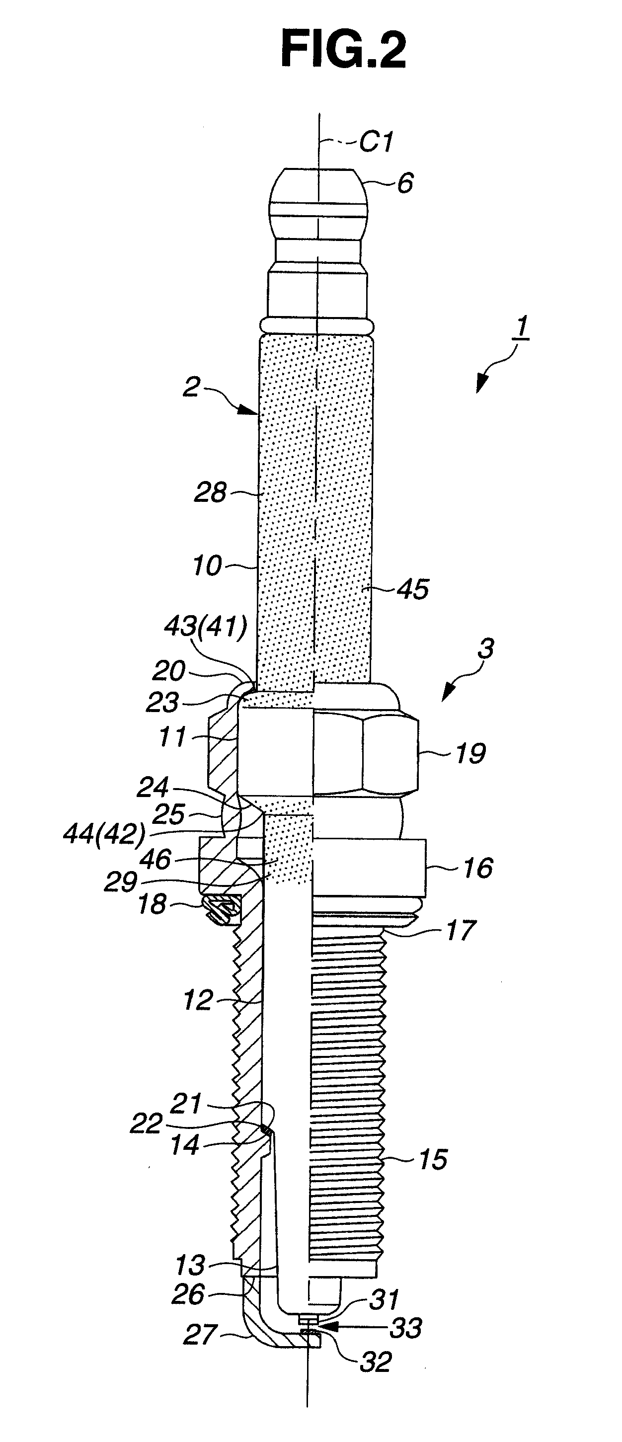
[0045]Fifty-two test samples of the spark plug 1 were manufactured by the above-mentioned procedure, except that the front glaze layer 29 was not formed (i.e. only the rear glaze layer 28 was formed). The thickness of the first body graze section 45 of the glaze layer 28 varied from sample to sample.

[0046]The test samples were subjected to bending strength test. The bending strength test was conducted as follows. The spark plug 1 was mounted on a test stand, with the axis of the spark plug 1 horizontally oriented, by screwing the thread portion 15 into a screw hole of the test stand with a tightening torque of 25 N·m. Using an autograph, a vertical load was applied from above to the terminal electrode 6. The load was gradually increased. The load under which a crack occurred in the ceramic insulator 2 was measured as a crack load. Further, the position of the crack in the ceramic insulator 2 was identified. The test results are indicated in FIG. 4. In FIG. 4, the triangular plots in...

experiment 2

[0048]Test samples of the spark plug 1 were manufactured by the above-mentioned procedure, except that the front glaze layer 29 was not formed (i.e. only the rear glaze layer 28 was formed). The thickness of the first corner graze section 43 of the glaze layer 28 varied from sample to sample.

[0049]The test samples were subjected to bending strength test in the same manner as above. The test results are indicated in FIG. 5. In FIG. 5, the triangular plots indicate the occurrence of cracking in the rear shoulder section 23 of the ceramic insulator 2 and the quadrangular plots indicate the occurrence of cracking in the middle body portion 12 of the ceramic insulator 2. Further, the first corner glaze thickness of 0 mm means the absence of the rear glaze layer 28.

[0050]As shown in FIG. 5, the rear shoulder section 23 of the ceramic insulator 23 was cracked even under relatively small loads when the thickness of the first corner glaze section 43 was less than 5 μm. When the thickness of ...


PUM


Abstract

There is provided a spark plug of an internal combustion engine, including a cylindrical metal shell, an insulator retained in the metal shell and having a through hole in an axial direction of the spark plug and a center electrode fitted in the through hole of the insulator. The insulator includes a rear body portion, a middle body portion and a large-diameter portion located between and protruded radially outwardly from the rear and middle body portions to define a rear shoulder section connected to the rear body portion and a front shoulder section connected to the middle body portion. For strength improvements, the insulator has a first glaze layer extending over the rear body portion and the rear shoulder section of the large-diameter portion and a second glaze layer extending over at least part of the middle body portion from some point on the front shoulder section of the large-diameter portion.

Description

BACKGROUND OF THE INVENTION[0001]The present invention relates to a spark plug of an internal combustion engine. Hereinafter, the term “front” refers to a spark gap side with respect to the direction of an axis of the spark plug, and the term “rear” refers to a side opposite the front side.[0002]A spark plug is generally provided with a cylindrical metal shell, a center electrode and an insulator and mounted on an internal combustion engine for reliable ignition of air-fuel mixture. The insulator has an axial through hole to hold therein the center electrode and includes a front leg portion, a middle body portion, a rear body portion and a large-diameter portion located between and protruded radially outwardly from the rear and middle body portions. The large-diameter portion of the insulator is often formed at a rear end thereof with a rear shoulder section in a curved surface form etc.[0003]The spark plug is exposed to various external stresses such as vibrations due to engine ope...

Claims


Application Information

Patent Timeline
IPC IPC(8): H01T13/38
CPCH01T13/38
Inventor MORIBE, MAISUZUKI, AKIRAHONDA, TOSHITAKA
Owner NGK SPARK PLUG CO LTD
Why Eureka
Try Eureka