Multi-mode RFID tag architecture

a tag architecture and multi-mode technology, applied in the field of communication systems, can solve the problems of inability to integrate rfid tags, large antennas of tag coils in comparison to other modules, and inability to detect rfid tags

Active Publication Date: 2008-10-02
NXP USA INC
View PDF3 Cites 116 Cited by
  • Summary
  • Abstract
  • Description
  • Claims
  • Application Information

AI Technical Summary

Problems solved by technology

Such tag coil antennas are large in comparison to the other modules of the RFID tag and are not able to be integrated on a chip, such as a complementary metal-o...

Method used


Image

  • Multi-mode RFID tag architecture
  • Multi-mode RFID tag architecture
  • Multi-mode RFID tag architecture

Examples


Embodiment Construction

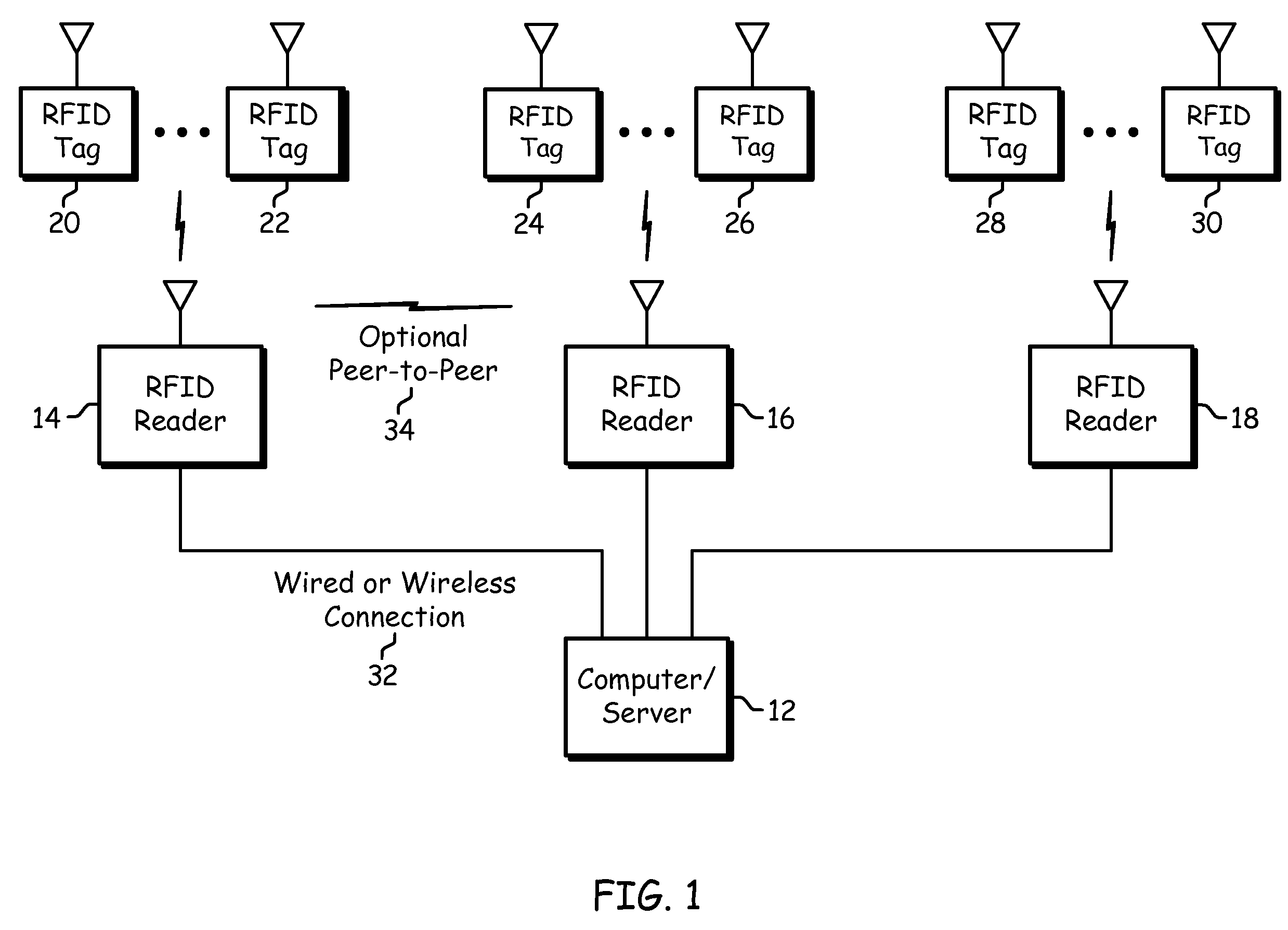
[0032]FIG. 1 is a schematic block diagram of an RFID (radio frequency identification) system that includes a computer / server 12, a plurality of RFID readers 14-18 and a plurality of RFID tags 20-30. The RFID tags 20-30 may each be associated with a particular object for a variety of purposes including, but not limited to, tracking inventory, tracking status, location determination, assembly progress, et cetera. The RFID tags may be active devices that include internal power sources or passive devices that derive power from the RFID readers 14-18.

[0033]Each RFID reader 14-18 wirelessly communicates with one or more RFID tags 20-30 within its coverage area. For example, RFID tags 20 and 22 may be within the coverage area of RFID reader 14, RFID tags 24 and 26 may be within the coverage area of RFID reader 16, and RFID tags 28 and 30 may be within the coverage area of RFID reader 18. In one mode of operation, the RF communication scheme between the RFID readers 14-18 and RFID tags 20-3...


PUM


Abstract

A multi-mode RFID tag includes a power generating and signal detection module, a baseband processing module, a transmit section, a configurable coupling circuit, and an antenna section. In near field mode, the configurable coupling circuit is operable to couple the transmit section to a coil or inductor in the configurable coupling circuit to transmit an outbound transmit signal using electromagnetic or inductive coupling to an RFID reader. In far field mode, the configurable coupling circuit is operable to couple the transmit section to the antenna section, and the multi-mode RFID tag then utilizes a back-scattering RF technology to transmit the outbound transmit signal to RFID readers.

Description

CROSS REFERENCE TO RELATED PATENTS[0001]This US patent application claims priority under 35 USC § 119 to a provisionally filed patent application entitled, “RFID System,” having a provisional filing date of Mar. 30, 2007, and a provisional application Ser. No. 60 / 921,221. This US patent application claims priority under 35 USC § 119 to a provisionally filed patent application entitled, “RFID System,” having a provisional filing date of May 31, 2007, and a provisional Ser. No. 60 / 932,411.STATEMENT REGARDING FEDERALLY SPONSORED RESEARCH OR DEVELOPMENT[0002]Not applicable.INCORPORATION-BY-REFERENCE OF MATERIAL SUBMITTED ON A COMPACT DISC[0003]Not applicable.BACKGROUND OF THE INVENTION[0004]1. Technical Field of the Invention[0005]This invention relates generally to communication systems and more particularly to RFID systems.[0006]2. Description of Related Art[0007]A radio frequency identification (RFID) system generally includes a reader, also known as an interrogator, and a remote tag...

Claims


Application Information

Patent Timeline
IPC IPC(8): G08B13/14
CPCG06K7/0008H04B5/0012H04B5/0062G06K19/07766G06K7/10198G06K19/073H04B5/0087G06K19/0724H04B5/00H04B5/02
Inventor ROFOUGARAN, MARYAMSHAMELI, AMIN
Owner NXP USA INC
Why Eureka
Try Eureka