Vehicle position detection system

a technology of position detection and vehicle, applied in traffic control systems, navigation instruments, instruments, etc., can solve problems such as reducing the range of error between, and achieve the effect of higher accuracy

Active Publication Date: 2008-10-02
HONDA MOTOR CO LTD
View PDF3 Cites 25 Cited by
  • Summary
  • Abstract
  • Description
  • Claims
  • Application Information

AI Technical Summary

Benefits of technology

[0007]Accordingly, it is an object of the present invention to provide a vehicle position detection system which can detect a vehicle position with higher accuracy.

Problems solved by technology

However, a range of error of the position detected based on the GPS signals is about 30 m. Therefore, there is a need to reduce the range of error between the detected position and an actual position.

Method used


Image

  • Vehicle position detection system
  • Vehicle position detection system
  • Vehicle position detection system

Examples


Embodiment Construction

[0034]The present invention will now be described in detail with reference to the accompanying drawings, wherein the same reference numerals will be used to identify the same or similar elements throughout the several views. It should be noted that the drawings should be viewed in the direction of orientation of the reference numerals.

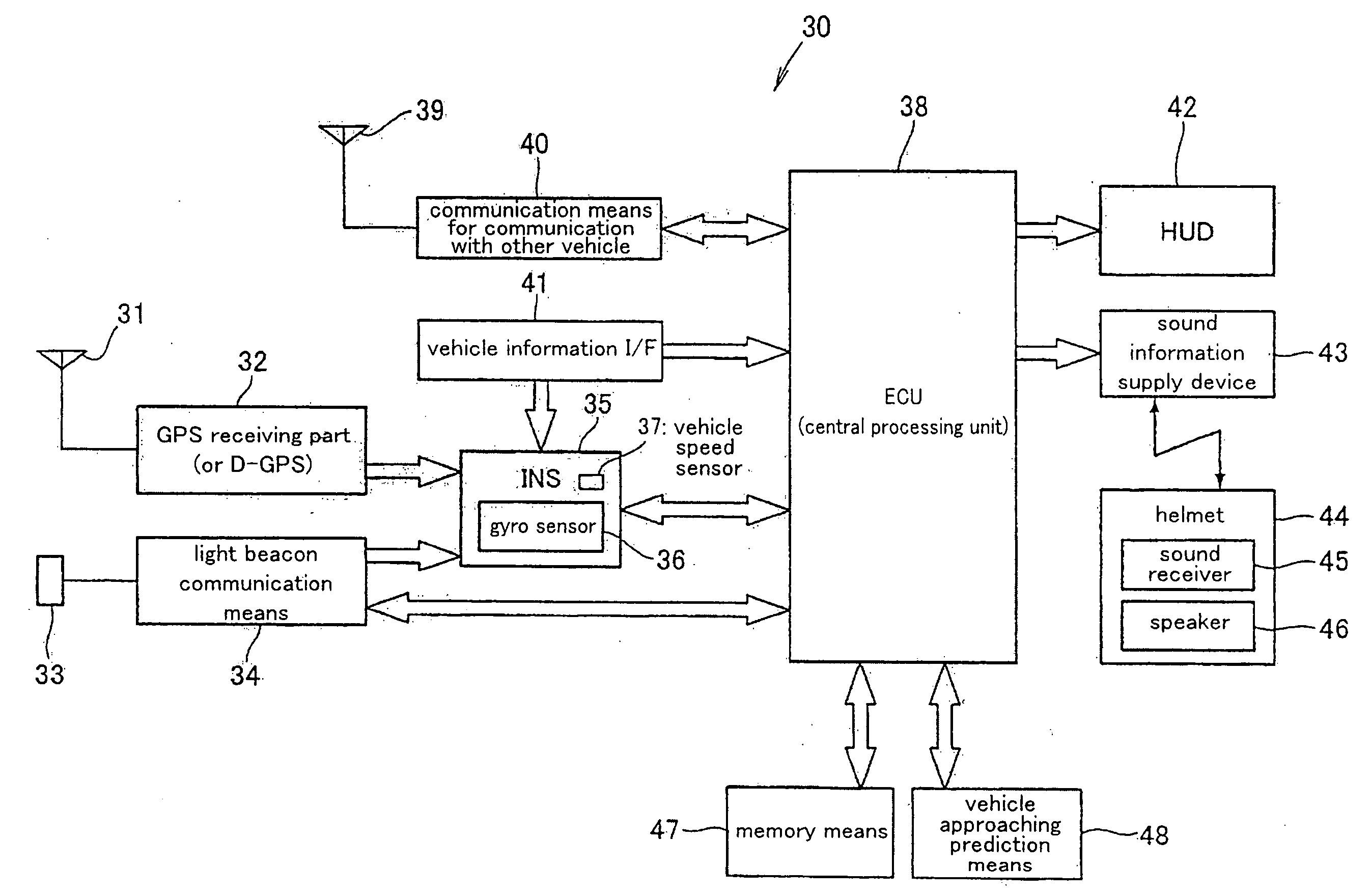
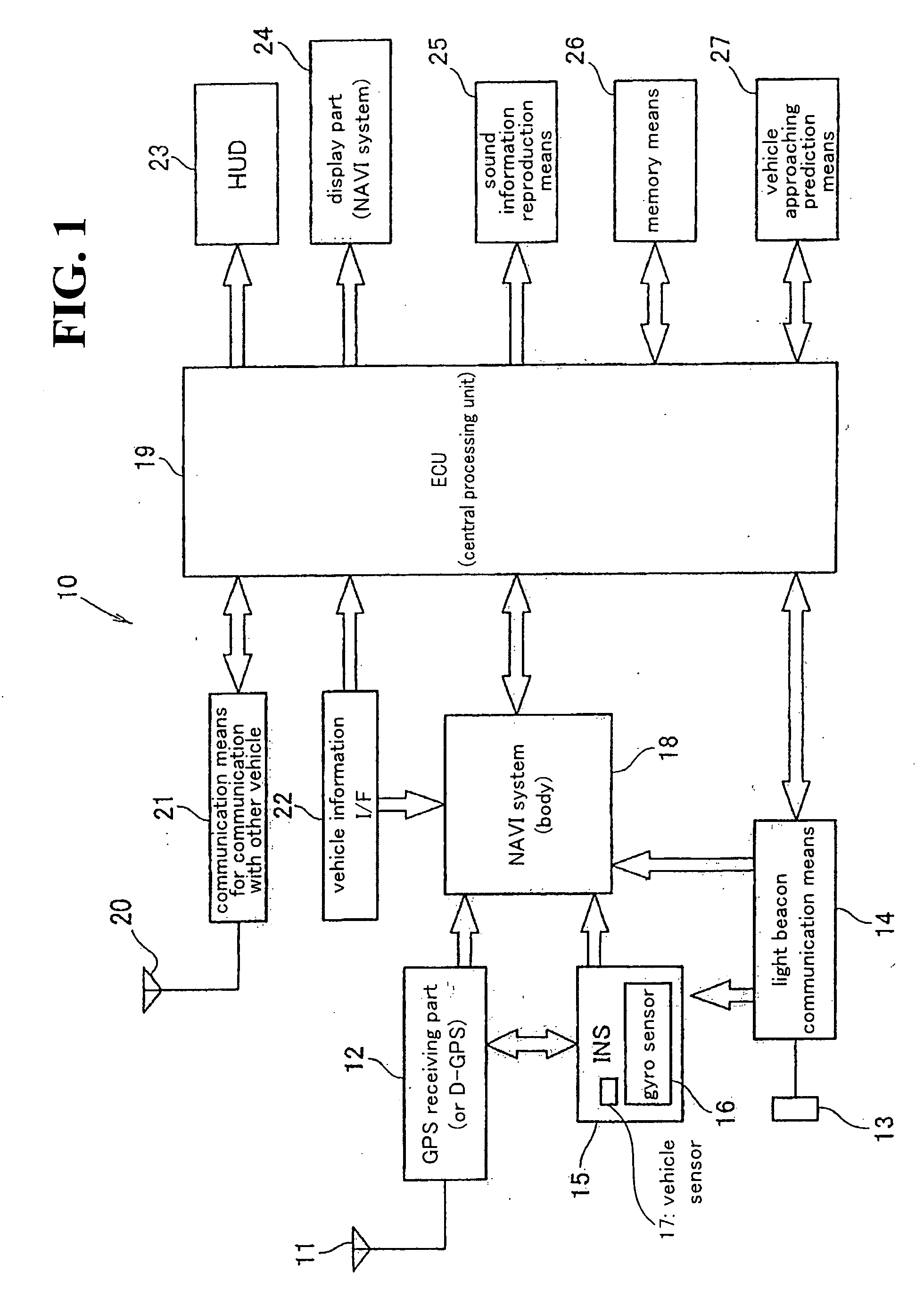
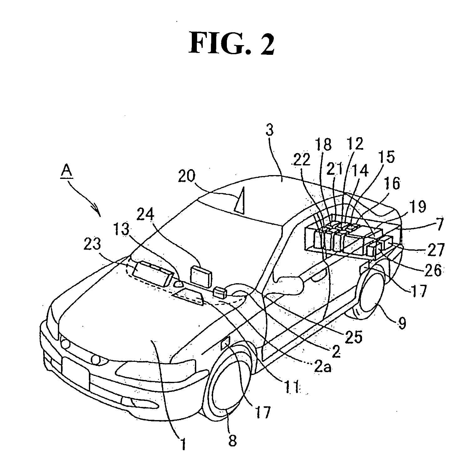
[0035]FIG. 1 is a block diagram of a vehicle position detection system according to the present invention which is mounted on a four-wheeled vehicle A. The vehicle position detection system 10 is a system for detecting a position of a vehicle. The vehicle position detection system 10 includes a GPS (Global positioning system) receiving part 12, a light beacon communication means or device 14, an inertia navigation system (INS) 15, a navigation (NAVI) system 18, and a central processing unit 19. The GPS (Global positioning system) receiving part 12 has an antenna 11. The light beacon communication means or device 14 has a light receiving part 13 for rec...


PUM


Abstract

A vehicle position detection system is provided to detect a vehicle position with higher accuracy. The vehicle position detection system includes a GPS receiving device mounted on the vehicle to receive GPS signals from a GPS satellite, a light beacon communication device mounted on the vehicle to receive light beacon information from a light beacon arranged in front of an intersection of a road, and a central processing unit mounted on the vehicle to correct a position of the vehicle based on the light beacon information upon reception of the light beacon information by the light beacon communication device.

Description

CROSS-REFERENCE TO RELATED APPLICATIONS[0001]This nonprovisional application claims priority under 35 U.S.C. § 119(a) on Patent Application No. 2006-268596, filed in Japan on Sep. 29, 2006, the entirety of which is incorporated herein by reference.BACKGROUND OF THE INVENTION[0002]1. Field of the Invention[0003]The present invention relates to a vehicle position detection system, and more particularly to a vehicle position detection system which detects a vehicle position by using GPS (Global positioning system) signals and light beacon information.[0004]2. Background of the Invention[0005]Conventionally, a device has been used to detect a position of a vehicle using GPS signals (see, for example, Japanese Patent 3773040 in FIG. 1, paragraph [0031]). As shown in FIG. 1 of Japanese Patent 3773040, a DGPS 13 receives GPS signals via an antenna ATgps and measures a present position of a vehicle.[0006]However, a range of error of the position detected based on the GPS signals is about 30...

Claims


Application Information

Patent Timeline
Patent Type & Authority Applications(United States)
IPC IPC(8): G01S5/00G01C21/00G01S19/48G01S19/05G01S19/14G01S19/49G08G1/09G08G1/0969G09B29/00G09B29/10
CPCG01C21/28G01S19/49G08G1/0962G01S19/485
Inventor KATAYAMA, MUTSUMIMARUYAMA, KAZUYUKIKUSHIDA, KAZUMITSU
Owner HONDA MOTOR CO LTD
Why Eureka
Try Eureka