Optical scanning device, optical scanning method, and image forming apparatus

a scanning device and optical scanning technology, applied in the direction of digitally marking record carriers, visual presentation using printers, instruments, etc., can solve the problems of fluctuation in light intensity, the rotational speed of the polygon motor and the frequency of the pixel clock cannot be further improved by a conventional technology, and the inability to set the light intensity of the laser diode to a desired valu

Inactive Publication Date: 2008-10-02
RICOH KK
View PDF23 Cites 63 Cited by
  • Summary
  • Abstract
  • Description
  • Claims
  • Application Information

AI Technical Summary

Benefits of technology

[0015]It is an object of the present invention to at least partially solve the problems in the conventional technology.

Problems solved by technology

However, the rotational speed of the polygon motor and the frequency of the pixel clock cannot be further improved by a conventional technology.
However, the relation between the drive current and light output from the laser diode depends on a temperature, and therefore it is difficult to set a light intensity of the laser diode to a desired value.
Therefore, it is likely to cause fluctuation in light intensity.
However, a problem occurs when images are printed on both surfaces of a sheet.

Method used


Image

  • Optical scanning device, optical scanning method, and image forming apparatus
  • Optical scanning device, optical scanning method, and image forming apparatus
  • Optical scanning device, optical scanning method, and image forming apparatus

Examples


first embodiment

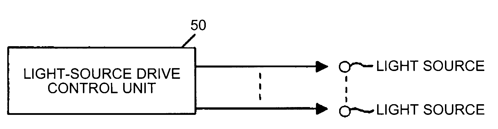
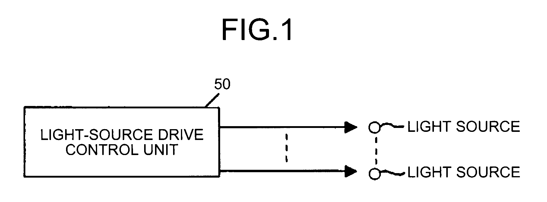
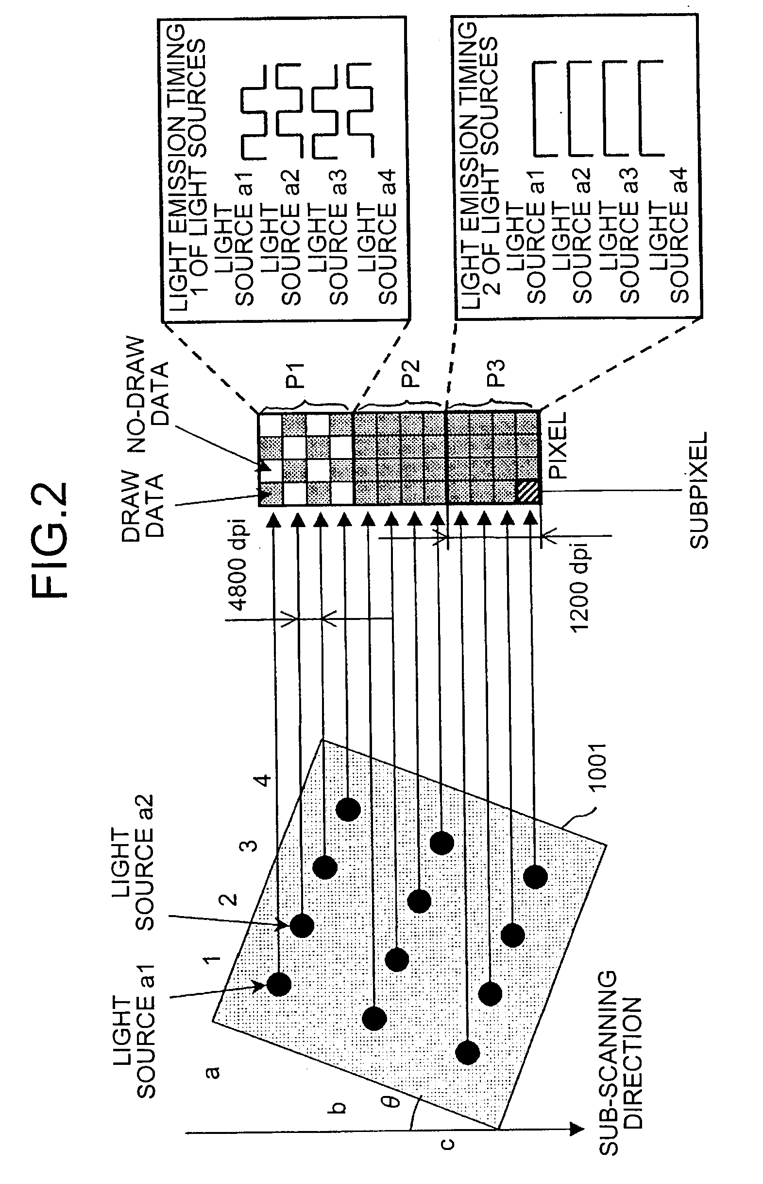
[0037]FIG. 1 is an example of a configuration of an optical scanning device according to the The optical scanning device scans a target surface in a main scanning direction with a plurality of light beams based on image data. The optical scanning device includes a plurality of light sources that emits the light beams, and a light-source drive control unit 50 that controls the light sources. The light sources are arranged at different positions in a sub-scanning direction. The image data includes a plurality of pixels, and each of the pixels includes a plurality of subpixels. One line of the subpixels is formed with a light beam emitted from a corresponding one of the light sources. The light-source drive control unit deletes certain subpixels from the image data in accordance with predetermined correction data, and shifts remaining subpixels in the sub-scanning direction in position of the deleted subpixels thereby obtaining reduced image data. The light-source drive control unit t...

second embodiment

[0069]The optical scanning device in the second embodiment scans a target surface in a main scanning direction with a plurality of light beams based on image data. The optical scanning device includes a plurality of light sources that emits the light beams, and the light-source drive control unit 50 that controls the light sources. The light sources are arranged at different positions in a sub-scanning direction. The image data includes a plurality of pixels, and one of the pixels includes a plurality of subpixels. One line of the subpixels is formed with a light beam emitted from a corresponding one of the light sources. The light-source drive control unit deletes certain subpixels from the image data in accordance with predetermined correction data, and shifts remaining subpixels in the sub-scanning direction in position of deleted subpixels, thereby obtaining reduced image data. The light-source drive control unit then controls the light sources based on the reduced image data.

[0...


PUM


Abstract

A light-source drive control unit divides each pixel of the image data into a plurality of subpixels, deletes certain subpixels from the image data in accordance with predetermined correction data, shifts remaining subpixels in the sub-scanning direction thereby obtaining reduced image data, and controls a plurality of light sources based on the reduced image data in such a manner that one line of the subpixels is formed with a light beam emitted from a corresponding one of the light sources.

Description

CROSS-REFERENCE TO RELATED APPLICATIONS[0001]The present application claims priority to and incorporates by reference the entire contents of Japanese priority documents 2007-090986 filed in Japan on Mar. 30, 2007 and 2007-090332 filed in Japan on Mar. 30, 2007.BACKGROUND OF THE INVENTION[0002]1. Field of the Invention[0003]The present invention relates to an optical scanning device, an optical scanning method, and an image forming apparatus.[0004]2. Description of the Related Art[0005]FIG. 17 is an example of a configuration of a conventional image forming apparatus (writing optical system). The conventional image forming apparatus is, for example, a laser printer or a digital copy machine. The conventional image forming apparatus performs electrophotographic process.[0006]A laser diode unit 1001 (light source unit) emits a laser beam, and the emitted laser beam is deflected by a polygon mirror 1002 that is rotating. The deflected laser beam passes through a scanning lens (fθ lens) ...

Claims


Application Information

Patent Timeline
Patent Type & Authority Applications(United States)
IPC IPC(8): G06F15/00
CPCG02B26/123G02B26/124H04N1/40068
Inventor TANABE, JUNISHIDA, MASAAKINIHEI, YASUHIROOMORI, ATSUFUMI
Owner RICOH KK
Why Eureka
Try Eureka