Variable Attenuator Device and Method

a variable attenuator and laser technology, applied in the direction of lasers, optical resonator shape and construction, manufacturing tools, etc., can solve the problems of unused laser radiation, shorten the lifetime of filters, and only produce discrete attenuation factors. limited and other problems, to achieve the effect of enhancing the nature and range of attenuation factors and extending the lifetime of attenuating devices

Inactive Publication Date: 2008-10-02
NIKON CORP
View PDF5 Cites 13 Cited by
  • Summary
  • Abstract
  • Description
  • Claims
  • Application Information

AI Technical Summary

Benefits of technology

[0005]The present invention provides a new and useful attenuating device and method for attenuating a polarized laser beam that addresses the foregoing issues, and also addresses other issues that are often associated with an attenuating device and method. The attenuating device and method of the present invention provides attenuating optics configured to reflect most of the unneeded light to a beam dump, where the unneeded radiation can be absorbed without harming the attenuating optics, thereby extending the lifetime of the attenuating device. Moreover, the attenuating optics can be adjusted to virtually any desired rotational orientation relative to the laser beam axis, and this feature enhances the nature and range of attenuation factors that can be produced.
[0006]In accordance with the present invention, at least one attenuating optic is located along, and is rotatable about, a polarized laser beam axis, and is configured to transmit and to reflect portions of the polarized laser beam. The attenuating optic provides predetermined attenuation of the polarized laser beam by changing the ratio between transmission and reflection of the polarized laser beam as a function of the incidence of the polarized laser beam on one or more partially reflective surfaces of the attenuating optic. The attenuating optic is rotatable about the polarized laser beam axis to control the incidence of the polarized laser beam on the one or more partially reflective surfaces of the attenuating optic, thereby to control the ratio between transmission and reflection of the polarized laser beam and provide a range of attenuation of the polarized laser beam.

Problems solved by technology

In an attenuation system designed to work with very high laser power, the unused radiation from the laser is an important issue.
With such a technique, the ND filters absorb a great deal of energy which shortens their lifetime.
Additionally the finite number of filters can only produce a limited number of discrete attenuation factors.

Method used


Image

  • Variable Attenuator Device and Method
  • Variable Attenuator Device and Method
  • Variable Attenuator Device and Method

Examples


Embodiment Construction

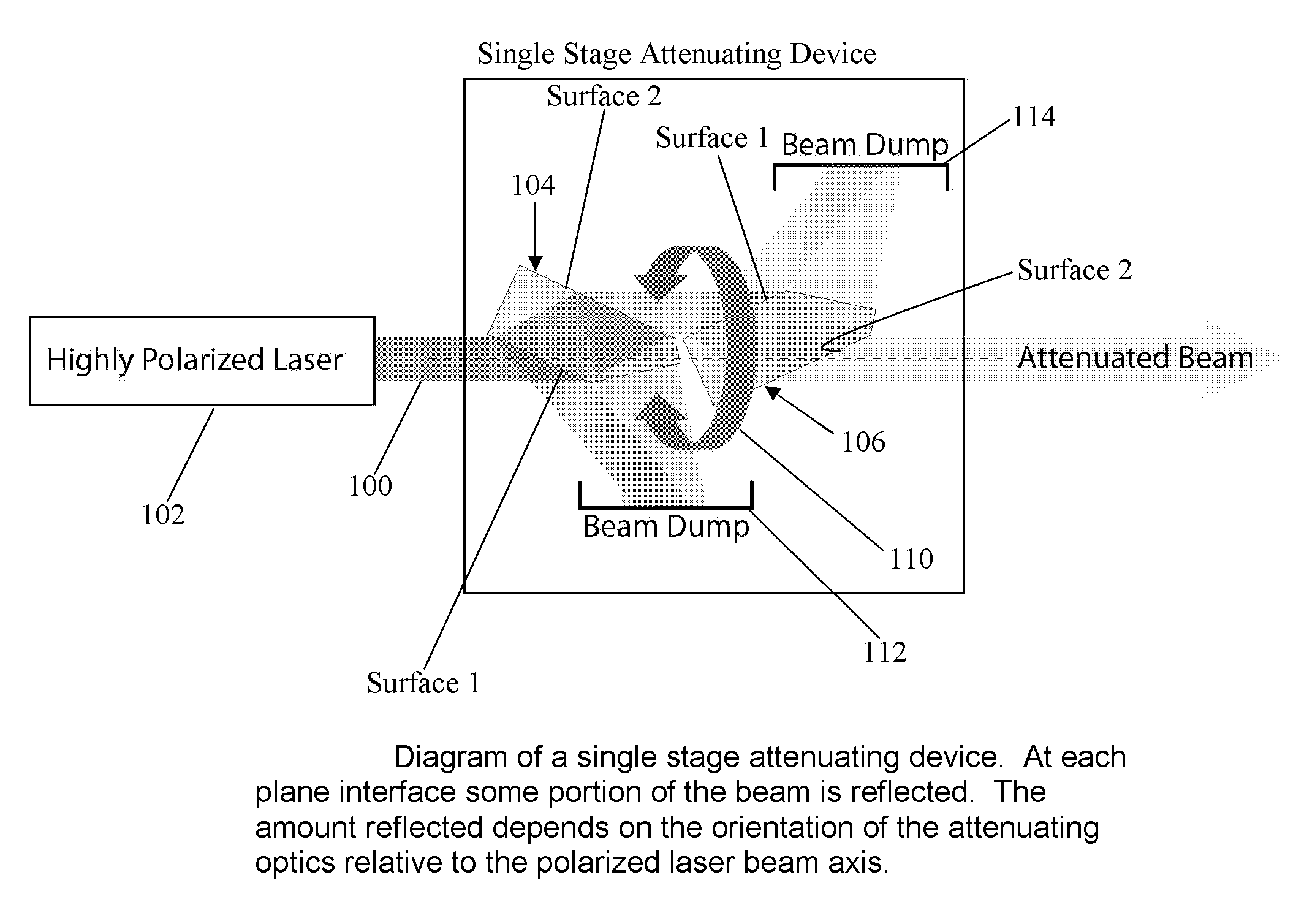
[0017]As described above, the present invention provides an attenuating device and method in which one or more attenuating optics provide reflection and / or transmittance of a polarized laser beam, to reflect unneeded laser light to beam dumps.

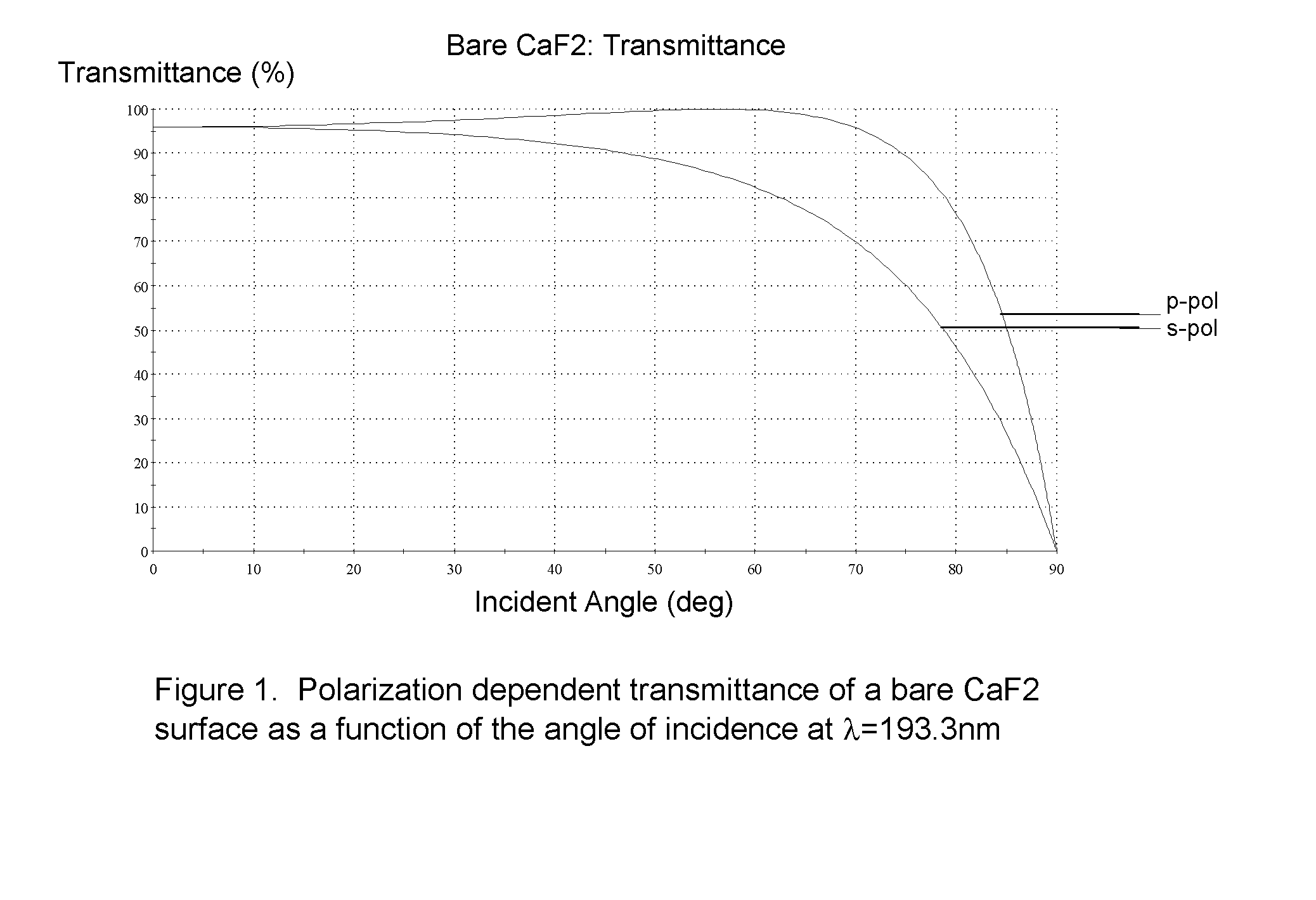
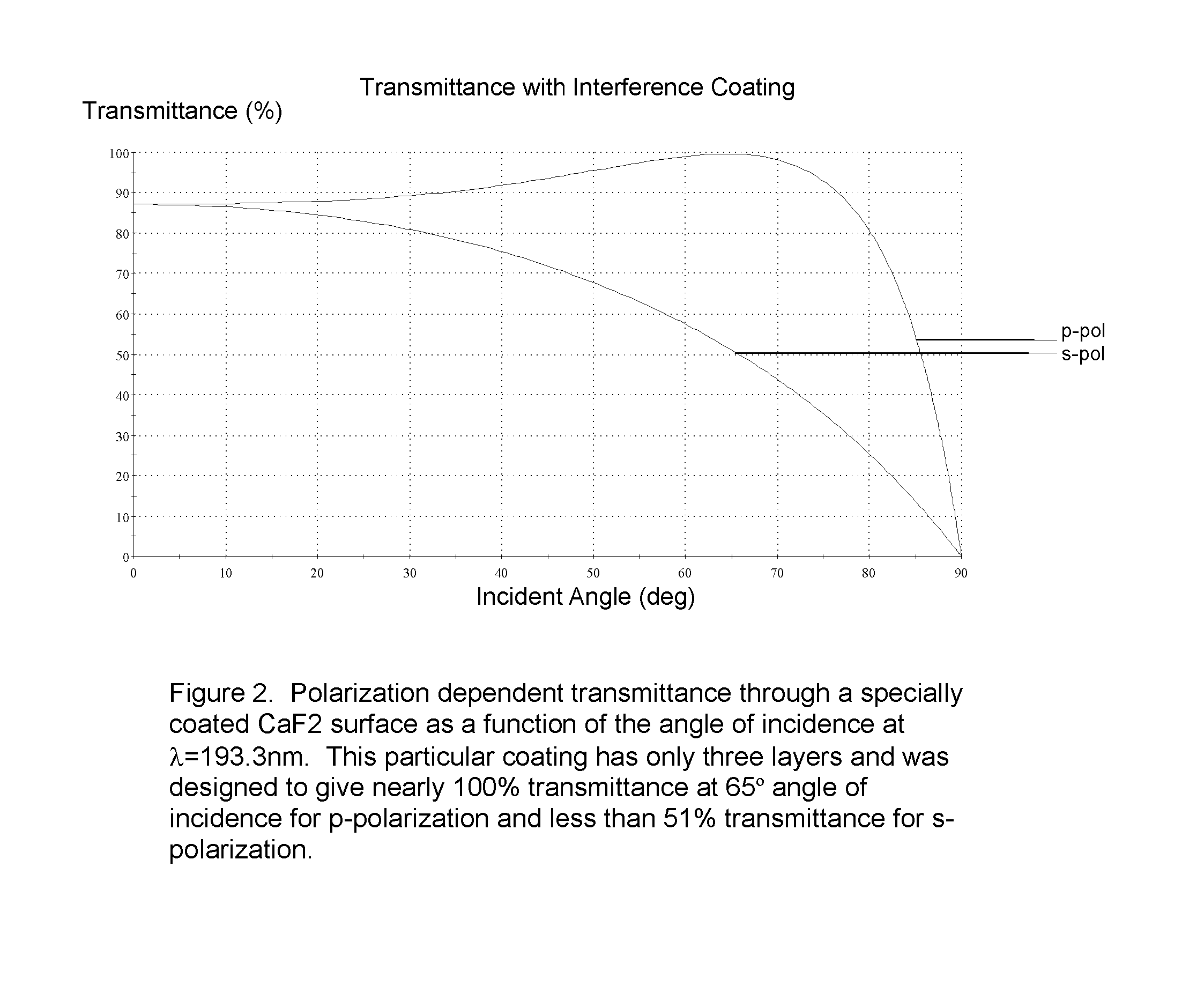
[0018]Initially, it is believed useful to note that the device and method of the present invention are partly based on the idea that the transmittance of a plane interface is different for p-polarization and s-polarization. This principle is illustrated for a bare Calcium Fluoride (CaF2) surface in FIG. 1, and it is possible to enhance this effect with interference coatings as shown in FIG. 2. According to the present invention, an interference coating that can be used with a Calcium Fluoride optic, to provide reflection of a portion of a polarized laser beam, would have the following composition:[0019]Incident medium—Air[0020]34.20 nm of LaF3 (n=1.701,k=0.0008)[0021]52.25 nm of AlF3 (n=1.390,k=0.0003)[0022]6.27 nm of LaF3 (n=1.701, k=0.0008)

[0...


PUM

PropertyMeasurementUnit
transmittanceaaaaaaaaaa
angle of incidenceaaaaaaaaaa

Abstract

A new and useful attenuating device and method for attenuating a polarized laser beam is provided. At least one attenuating optic is located along, and is rotatable about, a polarized laser beam axis, and is configured to transmit and to reflect portions of the polarized laser beam. The attenuating optic provides predetermined attenuation of the polarized laser beam by changing the ratio between transmission and reflection of the polarized laser beam as a function of the incidence of the polarized laser beam on one or more partially reflective surfaces of the attenuating optic. The attenuating optic is rotatable about the polarized laser beam axis to control the incidence of the polarized laser beam on the one or more partially reflective surfaces of the attenuating optic, thereby to control the ratio between transmission and reflection of the polarized laser beam and provide a range of attenuation of the polarized laser beam.

Description

RELATED APPLICATION / CLAIM OF PRIORITY[0001]This application is related to and claims priority from provisional application Ser. No. 60 / 920,002, filed Mar. 26, 2007, which provisional application is incorporated by reference herein.BACKGROUND[0002]The present invention relates to a new and useful device and method for producing attenuation of a laser beam, and particularly to providing variable attenuation of a polarized laser beam.[0003]In certain types of optical systems, it is desirable to provide attenuation of a polarized laser beam. For example, if the power of the polarized laser beam is too strong for the particular application, it is desirable to attenuate the polarized laser beam, to reduce the power of the beam that is used in the application.[0004]In an attenuation system designed to work with very high laser power, the unused radiation from the laser is an important issue. One known way of attenuating a polarized laser beam is to absorb a percentage of the laser beam pow...

Claims


Application Information

Patent Timeline
Patent Type & Authority Applications(United States)
IPC IPC(8): H01S3/13
CPCB23K26/0626H01S3/005
Inventor SMITH, DANIEL G.TANAKA, HIROHISAWILLIAMSON, DAVID M.
Owner NIKON CORP
Why Eureka
Try Eureka