Image scanning apparatus and image scanning method

a scanning apparatus and scanning method technology, applied in the field of scanning apparatus, can solve the problems of taking a long exposure time to obtain a satisfactory image, and the optical system adversely affecting the sensitivity of the image sensor, so as to improve the sensitivity to chemiluminescent or fluorescent light, shorten the exposure time, and achieve high-sensitivity imaging

Inactive Publication Date: 2008-10-02
FUJIFILM CORP
View PDF3 Cites 36 Cited by
  • Summary
  • Abstract
  • Description
  • Claims
  • Application Information

AI Technical Summary

Benefits of technology

[0024]The image scanning apparatus does not need any optical system for forming an image of the subject, because the subject is put in direct contact with the photoreceptive surface of the image sensor during the imaging. Therefore, the light from the subject will not suffer the attenuation through the optical system, so the image scanning apparatus of the invention achieves high-sensitive imaging. Because of the improved sensitivity to chemiluminescent or fluorescent light, it becomes possible to shorten the exposure time. Furthermore, no redundant space is necessary in the perpendicular direction to the photoreceptive surface of the image sensor, which has conventionally been necessary for forming an image on the photosensitive surface through the optical system. Thus, the image scanning apparatus of the present invention can be made thinner than conventional ones.

Problems solved by technology

However, the chemiluminescent light and the fluorescent light are so feeble and attenuate to such a low level through the optical system that it takes a long exposure time to obtain a satisfactory image even though the optical system uses lens elements of small f-numbers.
That is, the optical system adversely affects the sensitivity of the image sensor to the chemiluminescent or fluorescent light in the prior art.

Method used


Image

  • Image scanning apparatus and image scanning method
  • Image scanning apparatus and image scanning method
  • Image scanning apparatus and image scanning method

Examples


Embodiment Construction

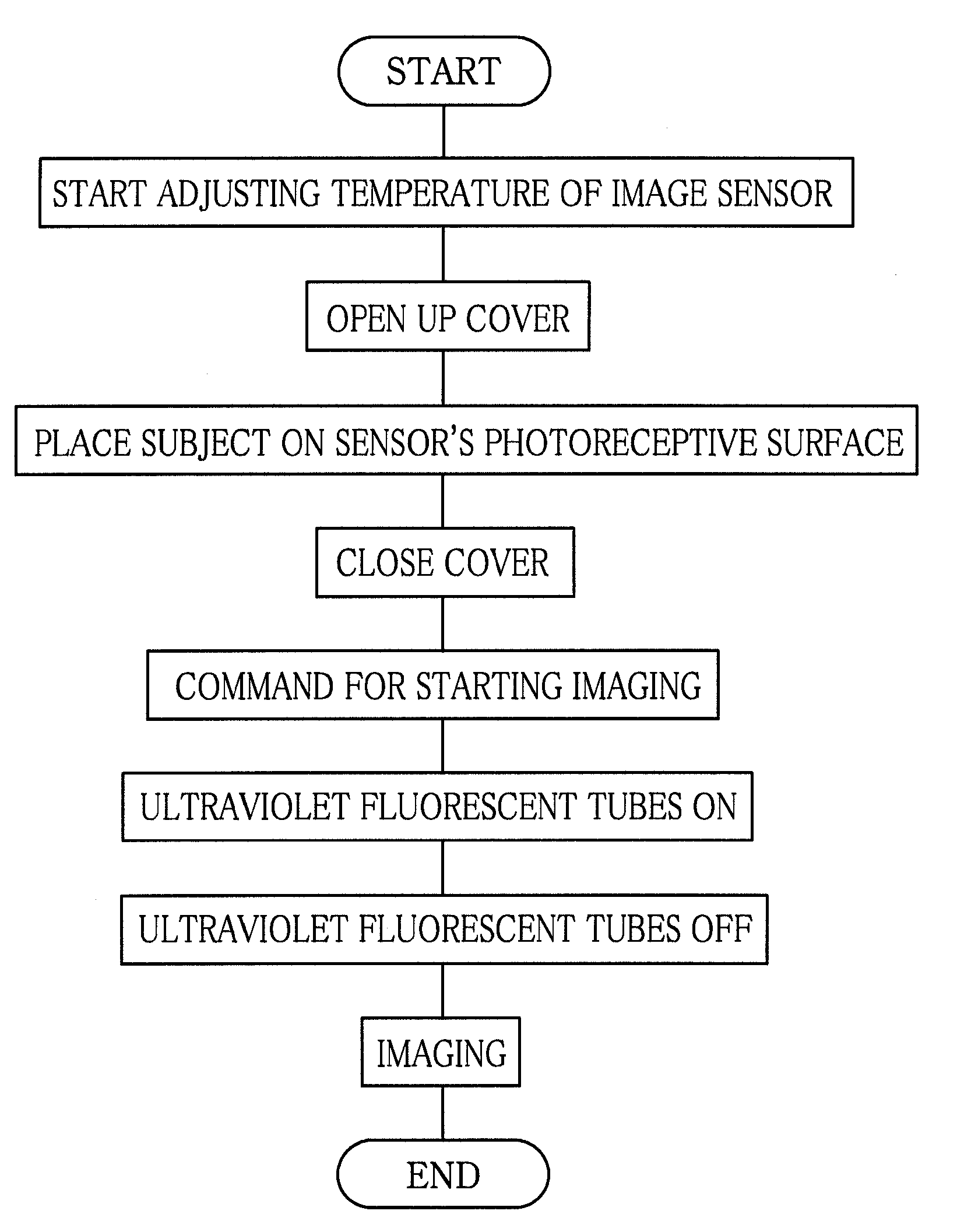
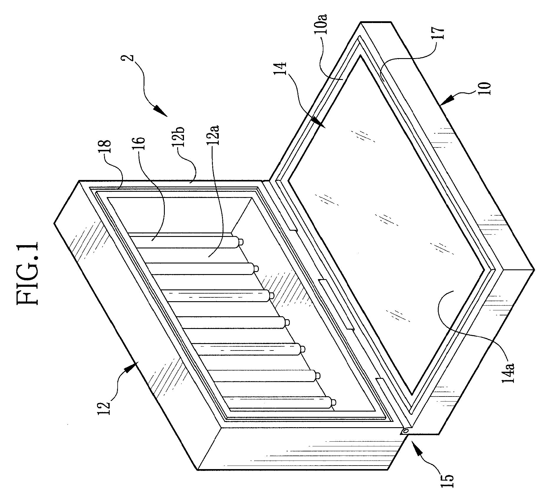
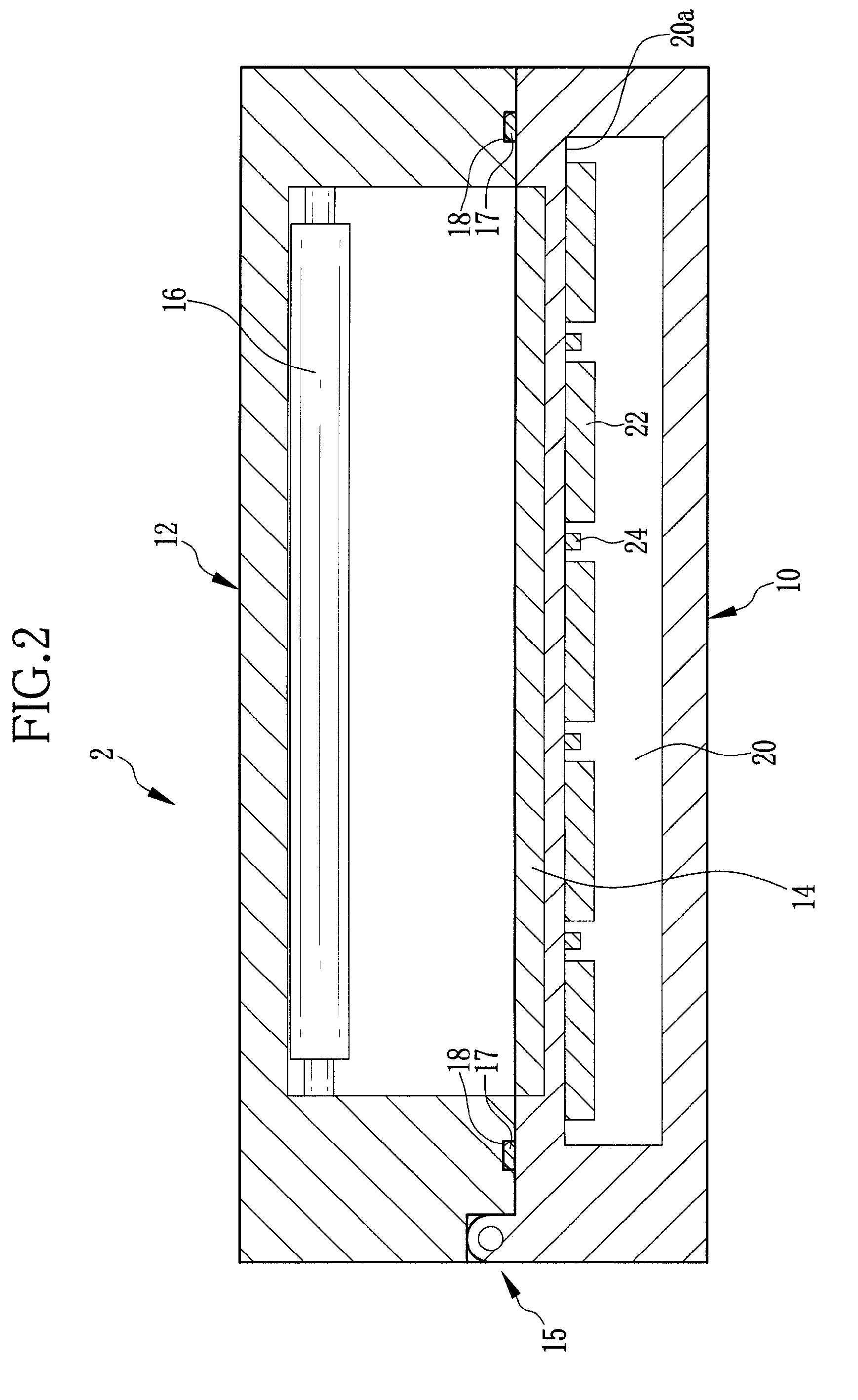
[0038]As shown in FIG. 1, an image scanning apparatus 2 is constituted of a base 10 for supporting a subject, and a cover 12 for covering up the subject on the base 10. The base 10 is shaped a substantially rectangular plate, whereas the cover 12 is shaped into a substantially parallelepiped box with an open side. An organic CMOS image sensor 14 is mounted in the base 10. The image sensor 14 has a photoreceptive surface 14a exposed on a top side or supporting side 10a of the base 10. The photoreceptive surface 14a is a rectangular surface of 10 cm×15 cm in this example, but its area size and shape are not limited to this example.

[0039]In the image scanning apparatus 2, a subject that is emitting light as being in contact with a chemiluminescent substance or a fluorochrome-labeled subject that is labeled with a fluorescent coloring material is directly placed on the photoreceptive surface 14a. Then the image sensor 14 is driven to scan the whole area of the photoreceptive surface 14a...


PUM


Abstract

An image scanning apparatus has an organic CMOS image sensor mounted in a base, and a photoreceptive surface of the image sensor is exposed on a top side of the base. A subject is placed directly on the photoreceptive surface, and the subject and the photoreceptive surface are covered up with a cover light-tightly. Thus the image sensor detects only chemiluminescent light from the subject. As for a fluorochrome-labeled subject, the subject placed directly on the photoreceptive surface is irradiated with excitation light from a light source mounted in the cover. The image sensor is provided with a filter for blocking the excitation light from its photoelectric conversion layers, so the image sensor detects only fluorescent rays generated from the excited fluorochrome-labeled subject. The image scanning apparatus needs no redundant space in perpendicular direction to the photoreceptive surface.

Description

FIELD OF THE INVENTION[0001]The present invention relates to an image scanning apparatus that captures an image from a subject containing a biological substance, the image representing a reactive condition of the biological substance. The present invention relates also to an image scanning method for the image scanning apparatus.BACKGROUND OF THE INVENTION[0002]Apparatuses that capture an image of a subject placed in a chassis while illuminating the subject with a light source have conventionally been used in many different application fields. In the field of biochemistry, an imaging apparatus, which uses a chemiluminescent substance or a fluorescent substance as a labeling material and reads out luminescence or fluorescence of the labeling material to detect gene sequences, level of gene expression, separation, identification or molecule weight of protein, or evaluate characteristics, has been known for example from JPA2005-283322.[0003]Concretely, for example, after adding a fluor...

Claims


Application Information

Patent Timeline
Patent Type & Authority Applications(United States)
IPC IPC(8): G03G15/16
CPCG01N21/6456G01N21/77
Inventor IKAMI, SEISHI
Owner FUJIFILM CORP
Why Eureka
Try Eureka