
Low-Noise Volume Flow Rate Throttling of Fluid-Carrying Pipes

Inactive Publication Date: 2008-10-02
AIRBUS OPERATIONS GMBH
View PDF15 Cites 8 Cited by
  • Summary
  • Abstract
  • Description
  • Claims
  • Application Information

AI Technical Summary

Benefits of technology

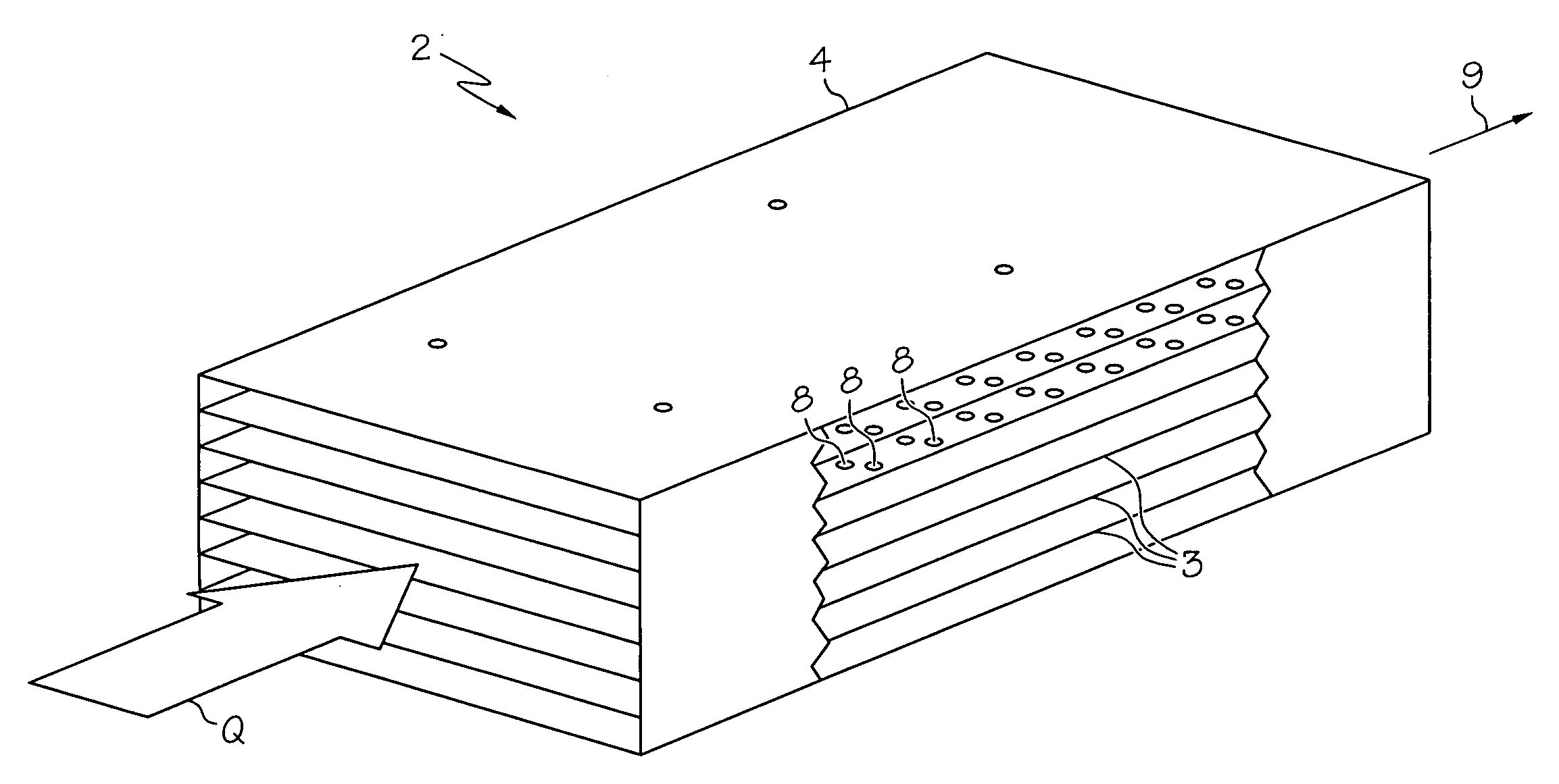
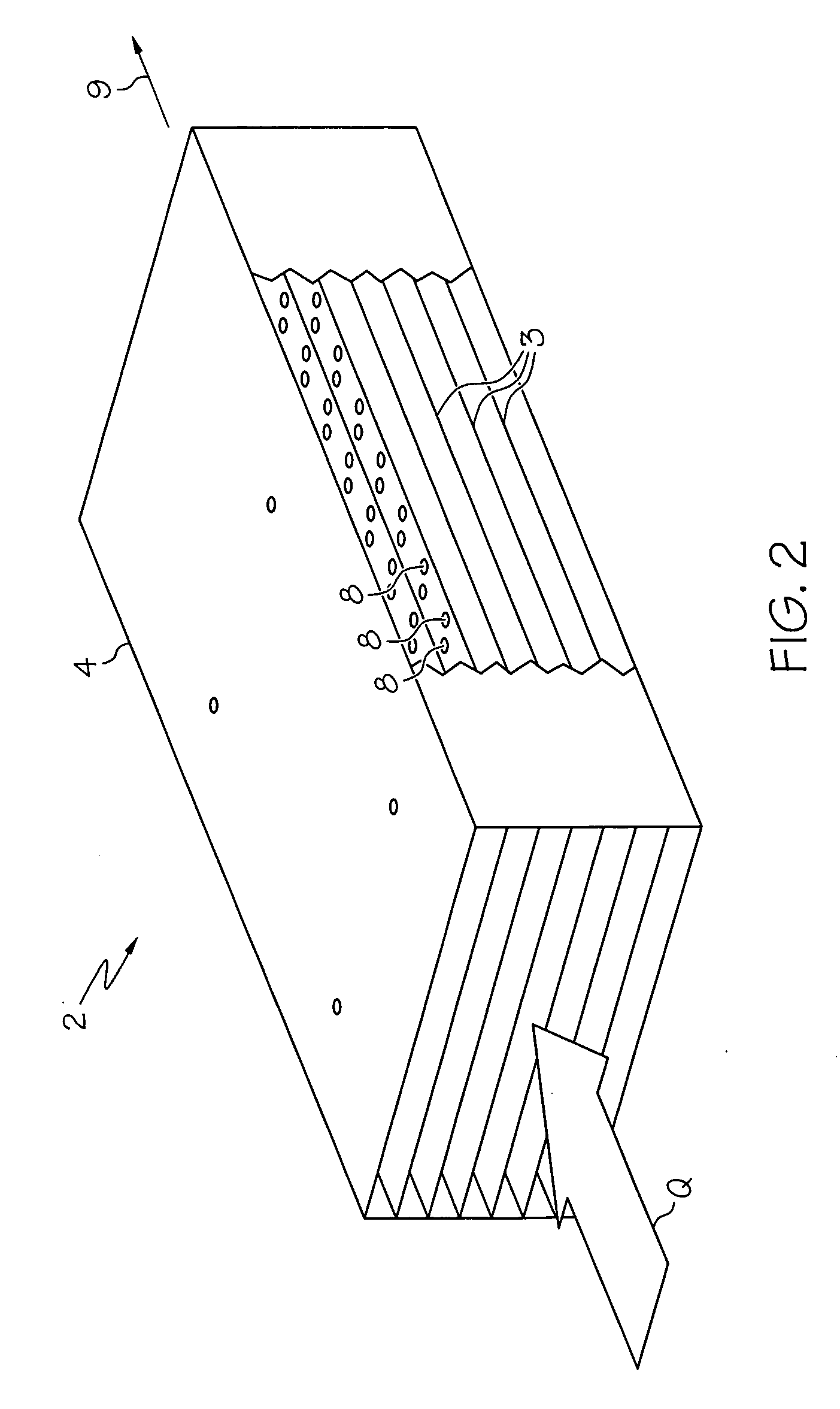
[0007]This object is achieved according to a first aspect of the present invention by a fluid throttle screen, which is adapted to control a fluid volume flow rate in a pipe and which has a plurality of friction elements extending longitudinally in a flow direction of the pipe. For this purpose, the individual friction elements of the plurality of friction elements are situated at a distance to one another in such a way that a fluid flowing against the fluid throttle screen is throttled continuously in its volume flow rate over the extension of the fluid throttle screen in the flow direction as a result of friction on the individual friction elements of the plurality of friction elements. In contrast to the known single-hole or multihole screens, the throttling does not occur punctually and abruptly at the screen here; rather, the inflow pressure of the fluid is throttled continuously and successively over the longitudinal extension of the fluid throttle screen according to the present invention, because of which there is no abrupt pressure drop nor the swirl formations accompanying it, which are responsible for the occurrence of a broadband noise level. The pressure reduction in the fluid throttle screen according to an exemplary embodiment of the present invention occurs via wall friction on the individual friction elements, so that through targeted dimensioning and implementation of the surface composition of the friction elements, undesired noise development may be avoided as much as possible.
[0008]In addition, the friction elements may be provided with holes which cause noise damping because of resonator effects, so that the fluid throttle screen additionally acts as a noise damper, which reduces the noise produced by the screen itself even further and, in addition, damps the noise occurring at other points of the climate control system, which is transmitted by the pipe in which the throttle screen is installed. The frequency range in which this damper effect is a maximum may be tailored to the requirements of the individual case by the hole geometry and the degree of perforation.
[0011]According to a further exemplary embodiment of the fluid throttle screen according to the present invention, the individual friction elements of the plurality of friction elements may be arranged or adapted as layered bodies as explained above, the individual layered bodies being situated in relation to one another in such a way that they mutually intersect in multiple intersection lines, however, which extend in the flow direction of the pipe, so that a honeycomb-like structure which may have flow through it results in the flow direction. In this way, multiple small flow channels are provided, which may contribute especially effectively to the pressure reduction over the fluid throttle screen.
[0014]According to a further aspect of the present invention, it is suggested that a throttle screen having at least some of the features as described above be used in a climate control system of an aircraft which comprises multiple pipe branches in order to control the fluid volume flow rate in at least one pipe branch. Through the use of the throttle screens according to the present invention in the climate control system of an aircraft, the typically resulting noise level may be reduced as much as possible and, in addition, by using the throttle screens according to the present invention, the air flowing out at an air outlet may be temperature-controlled entirely individually by an aircraft passenger.

Problems solved by technology

In addition, the friction elements may be provided with holes which cause noise damping because of resonator effects, so that the fluid throttle screen additionally acts as a noise damper, which reduces the noise produced by the screen itself even further and, in addition, damps the noise occurring at other points of the climate control system, which is transmitted by the pipe in which the throttle screen is installed.

Method used


Image

  • Low-Noise Volume Flow Rate Throttling of Fluid-Carrying Pipes
  • Low-Noise Volume Flow Rate Throttling of Fluid-Carrying Pipes
  • Low-Noise Volume Flow Rate Throttling of Fluid-Carrying Pipes

Examples


Embodiment Construction

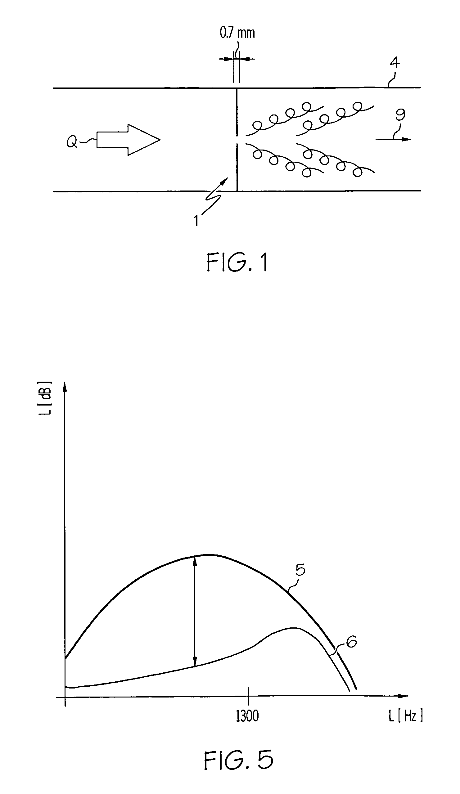
[0023]Firstly, a known single-hole screen as has been used until now for volume flow rate throttling in climate control systems will be described briefly with reference to FIG. 1. FIG. 1 shows a pipe branch 4 of a pipe system (not shown further) of a climate control system. A single-hole screen 1 is fitted in the pipe branch 4, which has a fluid flow Q flowing against it from the left. The single-hole screen 1 reduces the inflow Q in its quantity so that a reduced volume flow rate q flows after the single-hole throttle screen 1. Known single-hole throttle screens of this type have a very low thickness in the magnitude of 0.7 mm, which results in the volume flow rate being throttled down suddenly as a result of a very abrupt pressure drop, which causes a relatively strong swirl formation behind the single-hole screen 1. These swirls frequently result in a very strong noise development, which is to be avoided as much as possible, however.

[0024]In order to prevent noise development of ...


PUM


Abstract

The present invention relates to a fluid throttle screen for low-noise control of a fluid volume flow rate (Q) in a pipe and the use of such a throttle screen in an aircraft climate control system. In addition, the present invention relates to a climate control system in an aircraft in whose pipe system at least one such throttle screen is installed. The throttle screen according to the present invention comprises multiple friction elements extending longitudinally in the flow direction, which are situated at a distance to one another in such a way that a fluid is throttled continuously over the extension of the fluid throttle screen as a result of friction on the individual friction elements.

Description

REFERENCE TO RELATED APPLICATIONS[0001]This application is a U.S. National-Stage entry under 35 U.S.C. § 371 based on International Application No. PCT / EP2006 / 009400, filed 27 Sept. 2006, which was published under PCT Article 21(2) and claims the benefit of the filing date of German Patent Application No 10 2005 046 728.8 filed 29 Sept. 2005 and of U.S. Provisional Patent Application No. 60 / 722,024 filed 29 Sept. 2005, the disclosure of which applications is hereby incorporated herein by reference.TECHNICAL FIELD[0002]The present invention relates in general to the technical area of fluid mechanics and acoustics. In particular, the present invention relates to a fluid throttle screen, with which the volume flow rate in a fluid-carrying pipe may be reduced with low noise. Furthermore, the present invention relates to the use of such a throttle screen in an aircraft climate control system and a climate control system for an aircraft in which at least one fluid-carrying pipe branch is ...

Claims


Application Information

Patent Timeline
IPC IPC(8): B64D13/00F16L55/027
CPCB64D13/00F24F13/08F24F13/24
Inventor VIERTEL, MARTINBOOCK, KLAUS
Owner AIRBUS OPERATIONS GMBH
Learn More