Dual clutch transmission having reduced axial length

a clutch transmission and axial length technology, applied in mechanical equipment, transportation and packaging, gearing, etc., can solve the problems of reducing the ability to adjust the speed ratio, designer is forced to accept some ratios, and the axial space available for the transmission is limited, so as to achieve the effect of reducing the overall length

Active Publication Date: 2008-10-09
FORD GLOBAL TECH LLC
View PDF7 Cites 33 Cited by
  • Summary
  • Abstract
  • Description
  • Claims
  • Application Information

AI Technical Summary

Benefits of technology

[0006]The claimed invention is a dual clutch transmission which is intended for applications which have limited axial space available. The transmission has two countershafts, each with a final drive pinion that meshes with a common final drive ring gear. The gears on one of the countershafts (fifth, sixth, and reverse) are arranged as a cluster in a way that creates

Problems solved by technology

In a front wheel drive vehicle, the axial space available for the transmission is limited by the width of the engine compartment and the length of the engine.
A disadvantage of this method is that it reduces the ability to adjust speed ratios by selecting the size of each gear, because a change in the size of the pinion forces a change in the size of both driven gears.
This disadvantage is partially alleviated by the fact that there are two final drive ratios which can be adjusted separat

Method used


Image

  • Dual clutch transmission having reduced axial length
  • Dual clutch transmission having reduced axial length
  • Dual clutch transmission having reduced axial length

Examples


first embodiment

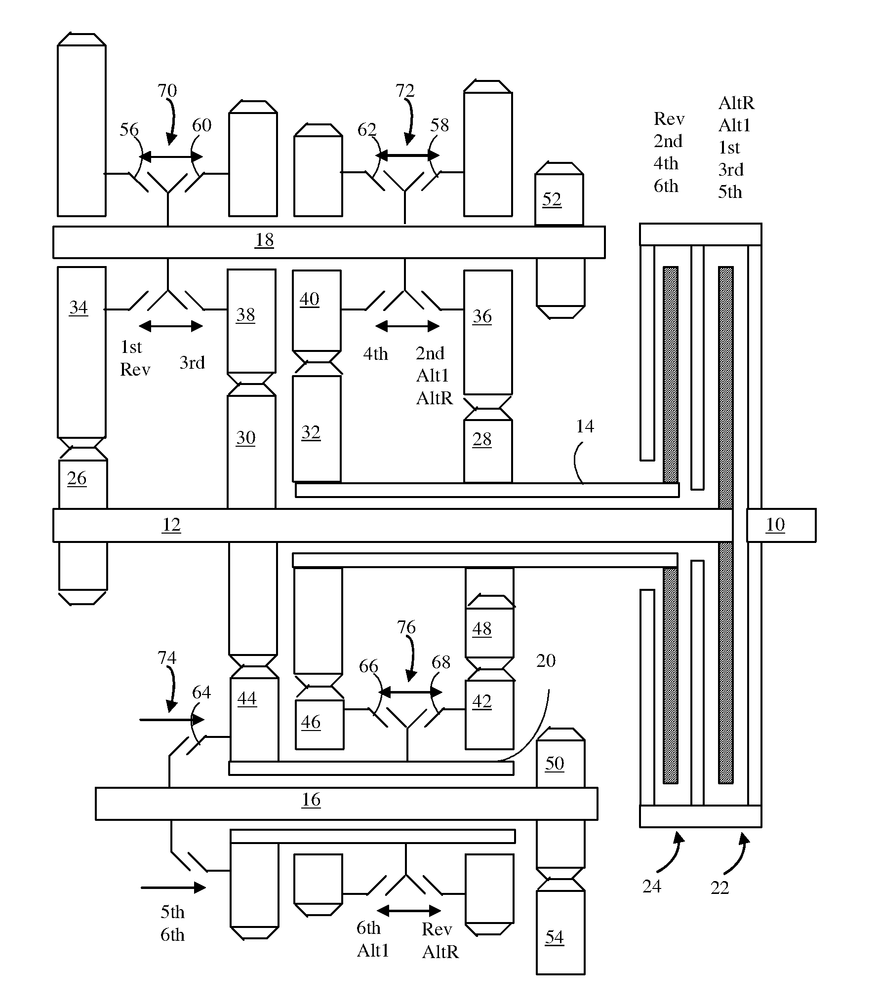
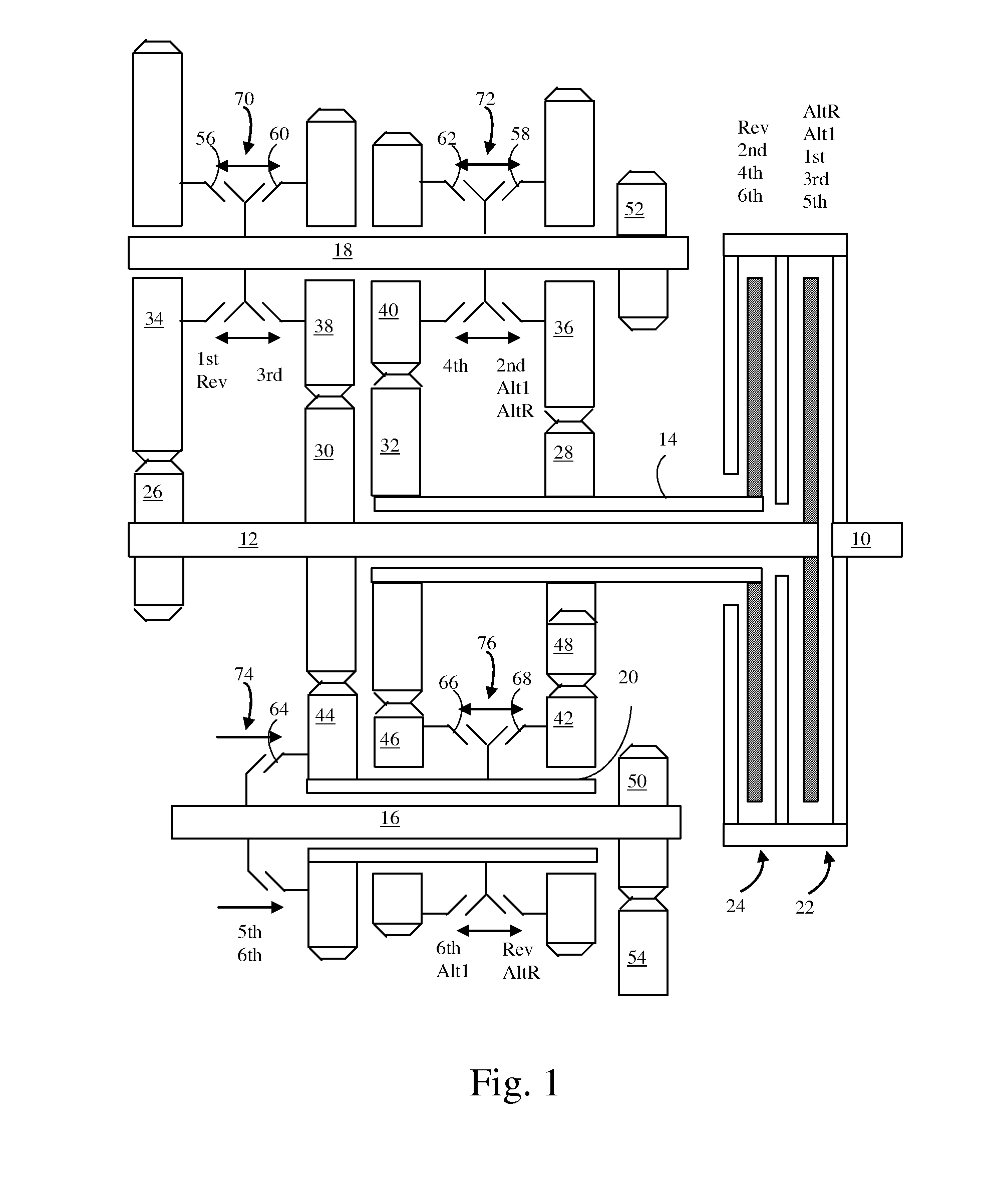
[0018]A transmission according to the present invention is illustrated in FIG. 1. A transmission input 10 is driven by the vehicle's engine. An odd clutch 22 releasably couples the transmission input to a solid input shaft 12. An even clutch 24 releasably couples the transmission input to a hollow input shaft 14 which is concentric with the solid input shaft. Countershafts 16 and 18 are arranged parallel to the input shafts. Output pinions50 and 52 are fixed to the countershafts and mesh with output ring gear 54. The output ring gear is fixed to the carrier of the differential unit (not shown) which drives both half shafts and the front wheels of the vehicle.

[0019]Pinions 26 and 30 are fixed to solid input shaft 12. Pinions 28 and 32 are fixed to hollow input shaft 14. Gear 34 is supported for rotation on countershaft 18 and in continuous meshing engagement with pinion 26. Gear 38 is supported for rotation on countershaft 18 and in continuous meshing engagement with pinion 30. Gear ...

third embodiment

[0032]FIG. 7 illustrates a third embodiment that obtains two additional forward speed ratios. It is derived from the embodiment illustrated in FIG. 1 by adding pinion 80 fixed to input shaft 12, gear 82 supported for rotation on countershaft 16, and coupler 84 which engages gear 82 with countershaft 16 whenever sleeve 74 is moved to the left. These parts could be added to the embodiment of FIG. 4 with similar results.

[0033]The transmission of FIG. 7 operates in a similar manner to the transmission of FIG. 1 up through sixth gear. The shift from sixth gear to seventh gear is accomplished by releasing clutch 24, moving sleeve 74 to the left to disengage gear 44 from countershaft 16 and engage gear 82 to countershaft 16, and then engaging clutch 22. This shift, unlike the shifts described above, requires the interruption of power to the wheels. Sleeve 76 should be maintained in the left position. A shift from seventh to eighth is accomplished by progressively releasing clutch 22 while ...


PUM


Abstract

A multiple speed power transmission comprises: an input; an output; first and second input shafts releasably coupled to the input by first and second friction clutches, respectively; a countershaft disposed parallel to the first and second input shafts; an output pinion fixed to the countershaft; an output ring gear fixed to the output and meshing with the output pinion; an intermediate shaft disposed coaxially with the countershaft; a first input pinion fixed to the first input shaft and meshing with a first gear fixed to the intermediate shaft; a second input pinion fixed to the second input shaft; a second gear disposed coaxially with the intermediate shaft; an idler gear meshing with the second input pinion and the second gear; a first coupler for releasably coupling the first countershaft to the intermediate shaft; and a second coupler for releasably coupling the intermediate shaft to the second gear.

Description

BACKGROUND OF THE INVENTION[0001]This invention relates to automatic transmissions having a layshaft kinematic arrangement, particularly to automatic transmissions having dual input clutches, but no torque converter.[0002]Dual clutch layshaft transmissions are essentially two automated manual transmissions in a common housing, one providing odd numbered gears and the other providing even numbered gears. Shifts between odd and even numbered gears can be accomplished without interrupting power flow. While operating in an odd numbered gear, couplers can be actuated to configure the transmission for the desired even numbered gear. Then, power is transferred to the even numbered gear by engaging the even clutch while disengaging the odd clutch in a coordinated fashion.[0003]In a front wheel drive vehicle, the axial space available for the transmission is limited by the width of the engine compartment and the length of the engine. For this reason, dual clutch transmissions typically use a...

Claims


Application Information

Patent Timeline
IPC IPC(8): F16H3/08
CPCF16H3/006F16H3/093F16H2003/0931F16H2200/0052F16H2200/0056Y10T74/19288F16H2200/0065F16H2200/0086Y10T74/19233Y10T74/19284Y10T74/19228F16H2200/006
Inventor BALDWIN, REID ALAN
Owner FORD GLOBAL TECH LLC
Why Eureka
Try Eureka