Multi-power source locomotive control method and system

a technology of locomotive control and power source, applied in the direction of dc source parallel operation, propulsion using engine-driven generators, electric devices, etc., can solve the problems of less effective medium-haul freight or commuter trains, and achieve the effect of substantial power and low emissions

Inactive Publication Date: 2008-10-09
RAILPOWER LLC
View PDF9 Cites 54 Cited by
  • Summary
  • Abstract
  • Description
  • Claims
  • Application Information

AI Technical Summary

Problems solved by technology

Hybrid locomotives can reduce emissions and fuel consumption in rail operations such as yard switching but they are less effective for medium haul freight or commuter trains.

Method used


Image

  • Multi-power source locomotive control method and system
  • Multi-power source locomotive control method and system
  • Multi-power source locomotive control method and system

Examples


Embodiment Construction

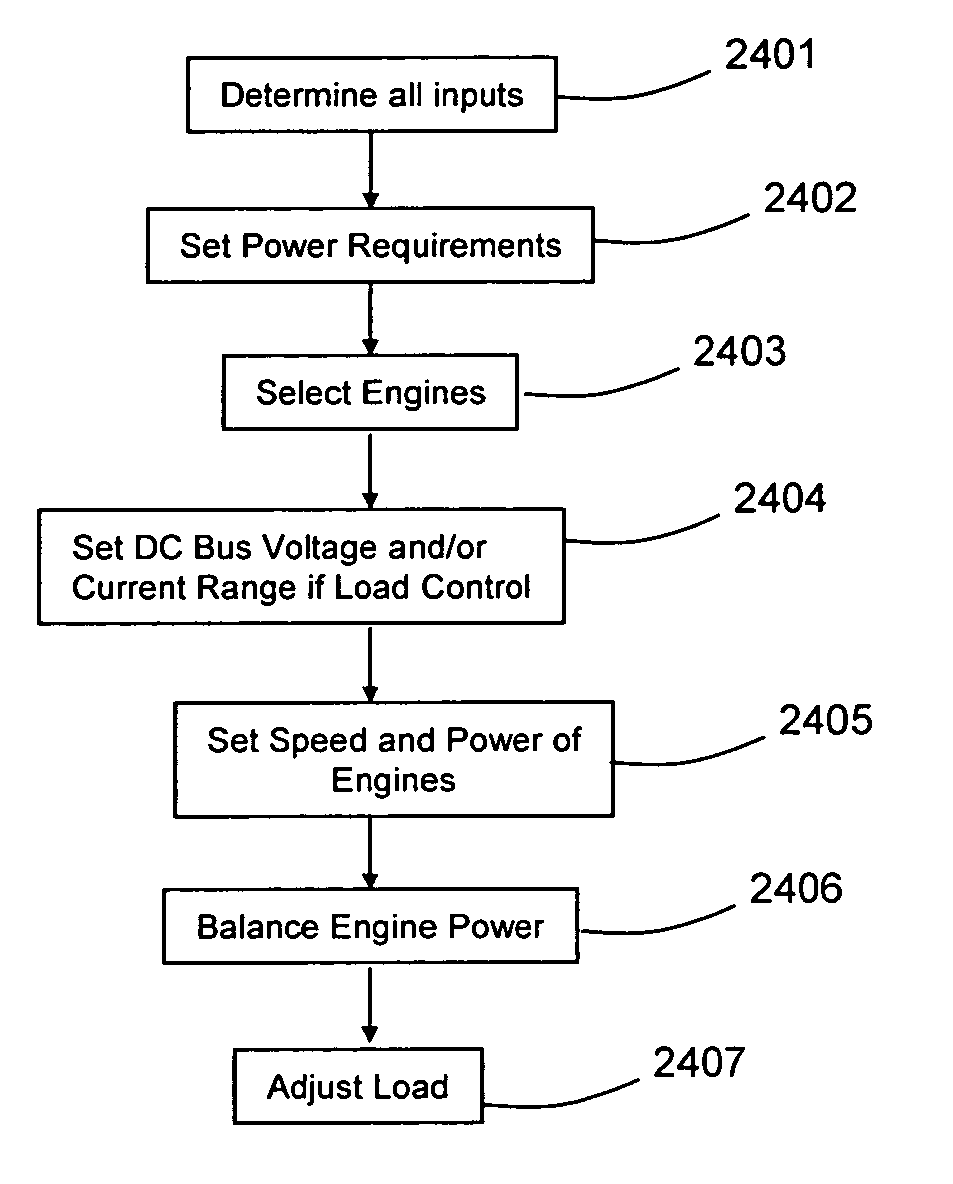
[0106]As shown in the attached figures, according to the present invention, there is provided a method of controlling a desired total system output power from a vehicle comprising a plurality of power sources, the plurality of power sources outputting DC electrical power to a common DC bus, and the vehicle also comprising a variable power control having a plurality of power settings. A shown in FIG. 10, the method comprises the steps of:[0107]a) selecting a number of power sources to be used according to a schedule to provide power to the DC common bus; 1002[0108]b) activating the power sources according to the schedule; 1003[0109]c) setting a desired range of a parameter indicative of power available on the DC common bus from at least one of voltage or current on the DC common bus; 1004[0110]d) measuring a signal corresponding to the parameter indicative of power available on the DC common bus from at least one of voltage or current on the DC common bus;[0111]e) for each of the plu...


PUM


Abstract

Control modes for operating multiple power sources include energy storage systems and applicable to large systems such as locomotives. Selectable operating modes are provided for different locomotive speed ranges and work loads. A common DC bus electrical architecture is used so that prime power sources need not be synchronized. Multiple-engine locomotives have the engine systems that may be electrically connected in parallel or in series or in combinations of parallel and series to a DC bus.

Description

[0001]The present application claims priority of U.S. Provisional patent application No. 60 / 886,465 filed Jan. 24, 2007, the contents of which are incorporated herein by reference.FIELD OF THE INVENTION[0002]The present invention relates generally to means of applying various control options for various control modes for a vehicle comprising a plurality of power sources and particularly to (1) a locomotive having a plurality of engines and (2) a locomotive having a plurality of engines and an energy storage system. The general method can be applied to a locomotive having a plurality of power sources, fuel types and drive train combinations. These methods pertain to multiple engine configurations where the engines may be connected in parallel to a common DC bus or in series to a common DC bus or in combinations of parallel and series to a common DC bus.BACKGROUND OF THE INVENTION[0003]Railroads are under increasing pressure to reduce emissions and to increase fuel efficiency. One of ...

Claims


Application Information

Patent Timeline
Patent Type & Authority Applications(United States)
IPC IPC(8): H02J1/10H02J1/00B60L50/10B60L50/11B60L50/15
CPCB60L11/02B60L2200/26B60L11/06B60L11/08B60L11/10B60L11/123B60L11/1801B60L11/1803B60L11/1805B60L2220/18B60L2260/165B61C7/04H02J1/10H02J1/14Y02T10/6217Y02T10/7005Y02T10/92Y02T30/16B60L11/04B60L1/003B60L1/02B60L7/12B60L7/14B60L7/22B60L15/32B60L2210/30B60L2210/40B60L2220/12B60L2220/14B60L2220/16B60L2220/20B60L2240/441B60L2240/443B60L2240/445B60L2260/26B60L2270/142B60L50/53B60L50/12B60L50/13B60L50/61B60L50/51B60L50/52Y02T30/00Y02T10/62Y02T10/70Y02T10/72
Inventor DONNELLY, FRANK WEGNERWATSON, JOHN DAVIDWOLFF, BRUCE
Owner RAILPOWER LLC
Why Eureka
Try Eureka