Luminescent device

Inactive Publication Date: 2008-10-09
TOYODA GOSEI CO LTD
View PDF3 Cites 83 Cited by
  • Summary
  • Abstract
  • Description
  • Claims
  • Application Information

AI Technical Summary

Benefits of technology

[0026]In the above-described headlight for the vehicle, the light source is mounted on the heat input portion of the heat pipe through the thermally conductive member. As a result, the heat of the light source is efficiently propagated to the heat input portion. Meanwhile, the heat dissipation portion of the heat pipe is connected to the vehicle frame or the heat exchanger. Since the vehicle frame and the heat exchanger have large heat capacities, the h

Problems solved by technology

Such a change of the installation angle involves complicated operation.
In addition, it is difficult to

Method used


Image

  • Luminescent device
  • Luminescent device
  • Luminescent device

Examples


first embodiment

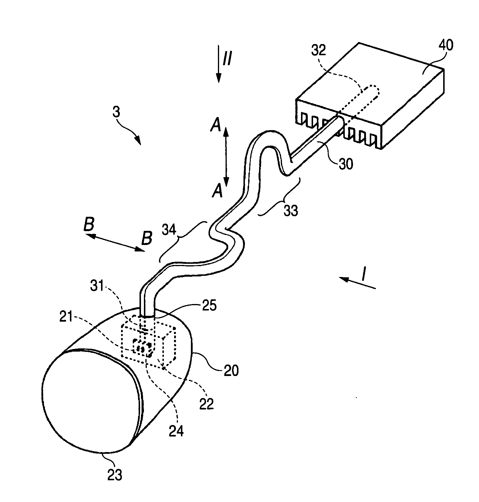
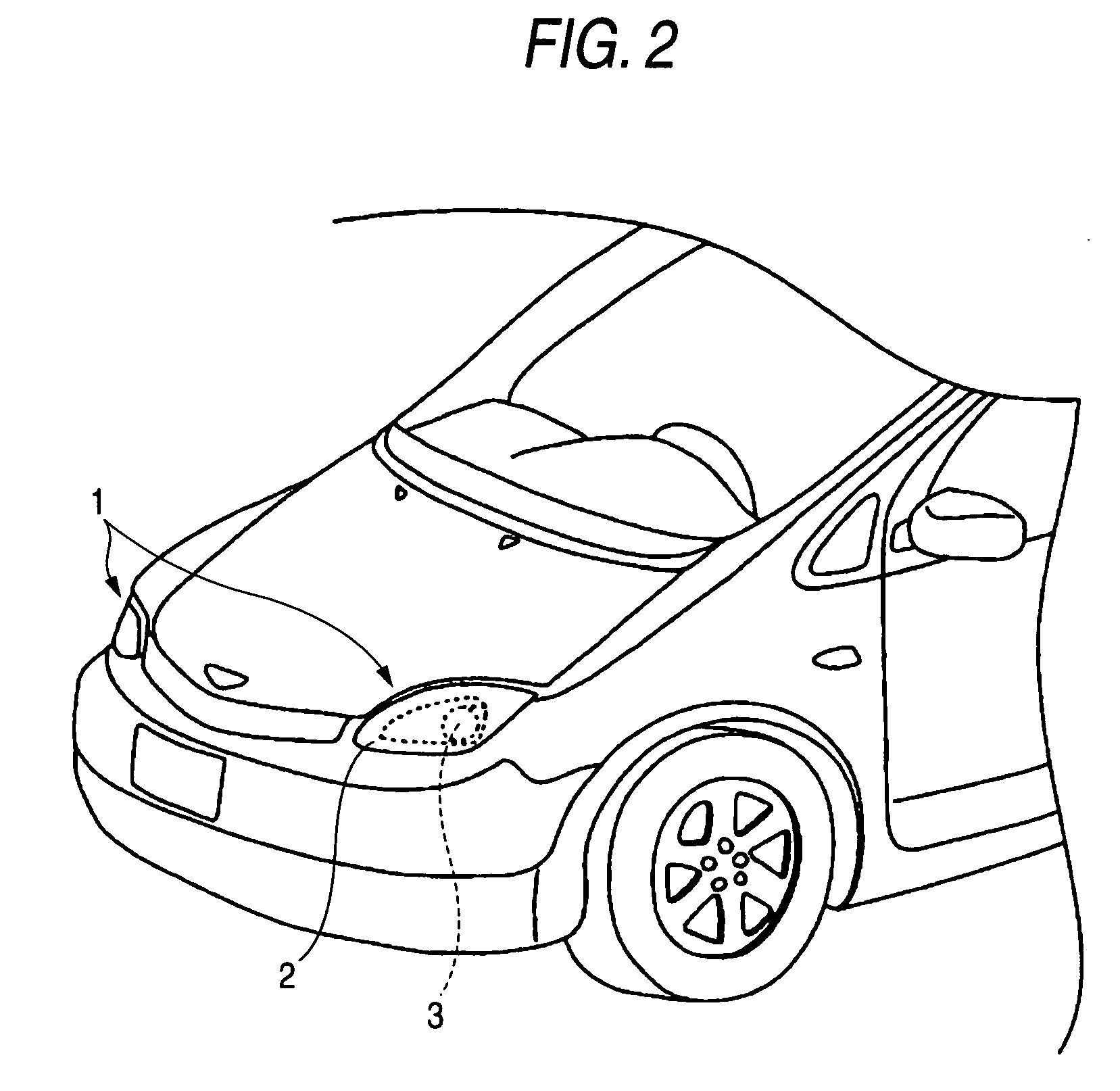
[0067]FIG. 2 shows a perspective view of a headlight 1 of a vehicle according to a first embodiment of the invention. As shown in FIG. 2, the headlight 1 has an outer lens 2 and a light source unit 3. FIG. 3 shows a perspective view of the light source unit 3 of the headlight 1. As shown in FIG. 3, the light source unit 3 is comprised of a housing 20, a heat pipe 30, and a heat sink 40. The housing 20 has a light source 21 accommodated therein. The light source 21 is mounted on one end portion (heat input portion 31) of the heat pipe 30 through a heat conducting member 22. The heat conducting member 22 is formed of aluminum. A lens 23 is provided on the light emitting side of the light source 21 of the housing 20. The light source 21 is a white light emitting LED lamp of a surface mounted type. It should be noted that, by taking the heat dissipation characteristic into consideration, a ceramic-made substrate is adopted as a mounting substrate 24 on which an LED chip is mounted. The ...

second embodiment

[0074]FIG. 5A shows a partially cross-sectional view, taken from a lateral direction, of a downlight 50 according to a second embodiment of the invention. FIG. 5B shows a partially cross-sectional view taken from an angle shown at III in FIG. 5A. The downlight 50 is embedded in an indoor ceiling. The downlight 50 is comprised of a reflector 51, a housing 200, a heat pipe 300, and a heat sink 400. The reflector 51 has the shape of a bowl and is installed so as to be open to the indoor side. The housing 200 is installed in a deepest portion of the reflector 51. The housing 200 has a light source 210 accommodated therein. The light source 210 is mounted on one end portion (heat input portion 310) of the heat pipe 300 through a heat conducting member 220. A lens 230 is provided on the light emitting side of the light source 210. The light source 210 is a white light emitting LED lamp of the surface mounted type. The heat pipe 300 has the heat input portion 310 disposed on one end side f...

third embodiment

[0078]FIG. 8 shows a vertical cross-sectional view of a headlight 800 for a vehicle according to a third embodiment of the invention. The headlight 800 is comprised of a housing 820, an outer lens 826, a heat pipe 830, a heat sink 840, and a light source unit 850. The light source unit 850 has a base 824 of a flat plate shape, and a light source 821 is provided on a seat portion in its center. The light source 821 is a white LED lamp. The light source unit 850 has a lens 823 provided on the front side (in a direction facing the outer lens 826). A reflector 851 is provided on the light emitting side of the light source 821. The reflector 851 has a semi-dome shape in which the front side is open, and reflects the light of the light source 821 in the direction toward the lens 823.

[0079]A part of the light source unit 850, the heat pipe 830, and the heat sink 840 are extracted, and a perspective view thereof is shown in FIG. 9. As shown in FIGS. 8 and 9, the base 824 is fixed to the hou...


PUM


Abstract

A luminescent device includes: a light source; a housing for accommodating the light source, a heat discharging member including a heat transfer portion and a heat dissipation portion and passed through the housing, the heat transfer portion being mounted on the light source and the heat dissipation portion being located outside the housing; a seal portion for sealing a gap between the heat discharging member and the housing; and optical axis adjusting device for adjusting an optical axis of the light source, wherein the heat transfer portion or the seal portion is deformed so as to follow an angular change of the optical axis of the light source by the optical axis adjusting device.

Description

BACKGROUND OF THE INVENTION[0001]1. Field of the Invention[0002]The present invention relates to a luminescent device, and more particularly to the improvement of a heat dissipation mechanism of a luminescent device served as a headlight for a vehicle, for example.[0003]2. Related Art[0004]Luminescent devices are used in various applications including indoor lighting fixtures and lamp fittings for vehicles, but countermeasures against heat are important in luminescent devices used in indoor lighting fixtures and lamp fittings such as a vehicle headlight whose quantities of light are large. As a countermeasure against heat, one using a heat pipe is known. For example, JP-A-2006-107875 discloses a luminescent device having a heat pipe in which a heat input portion is attached to a light source in a housing, and a heat discharging portion is attached to a heat sink outside the housing. In this luminescent device, heat generated from the light source is released to outside the housing b...

Claims


Application Information

Patent Timeline
IPC IPC(8): F21V29/00
CPCF21S8/02F21S8/026F21S48/1154F21S48/1159F21S48/1742F21V29/76F21V14/02F21V21/14F21V29/004F21Y2101/02F21V29/006F21S48/328F21V29/71F21Y2115/10F21S41/143F21S41/148F21S41/657F21S45/48F21S45/50F21V15/01
Inventor TANAKA, YOSHIHARUADACHI, TAKAOMISAWA, AKIHIROYABUYA, SHIGERUSHIBATA, MINORU
Owner TOYODA GOSEI CO LTD
Why Eureka
Try Eureka