

System and method to measure cardiac ejection fraction
a technology of cardiac ejection fraction and system, applied in the field of medical-based ultrasound, can solve the problems of large size of the existing machine for obtaining echocardiography (ecg)-based data, inconvenient operation, and high cos
- Summary
- Abstract
- Description
- Claims
- Application Information
AI Technical Summary
Benefits of technology
Problems solved by technology
Method used
Image

Examples
Embodiment Construction
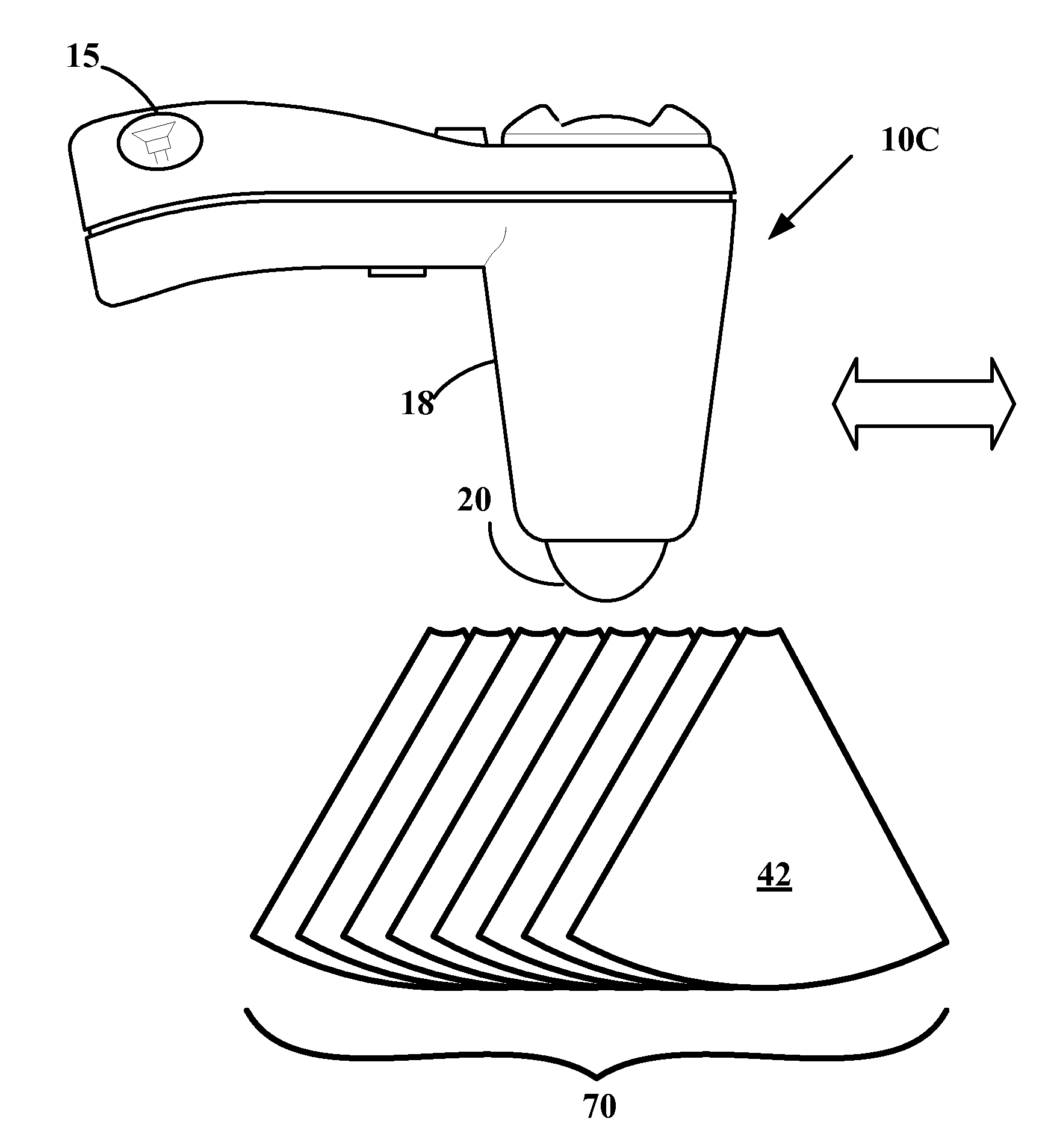
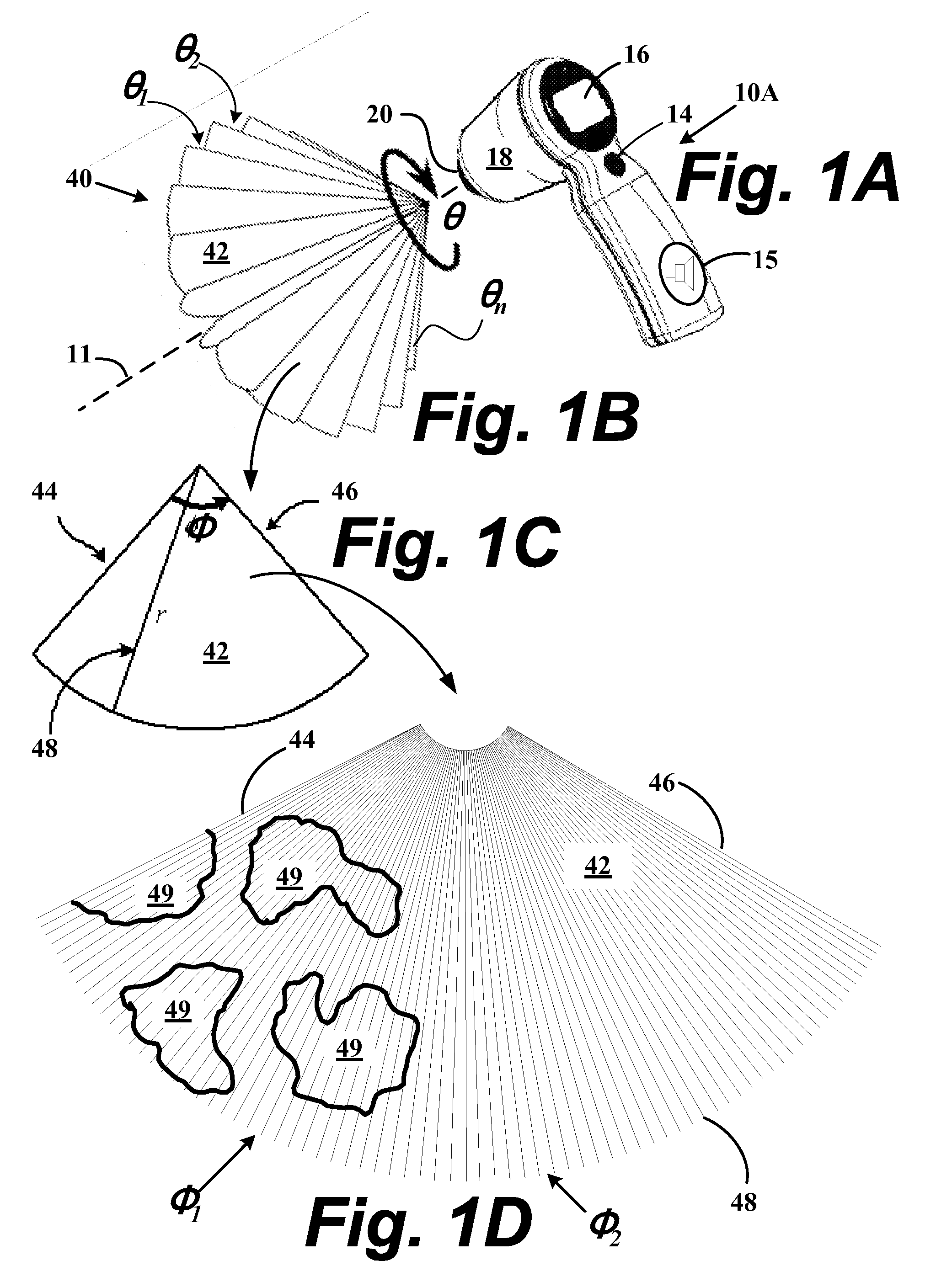
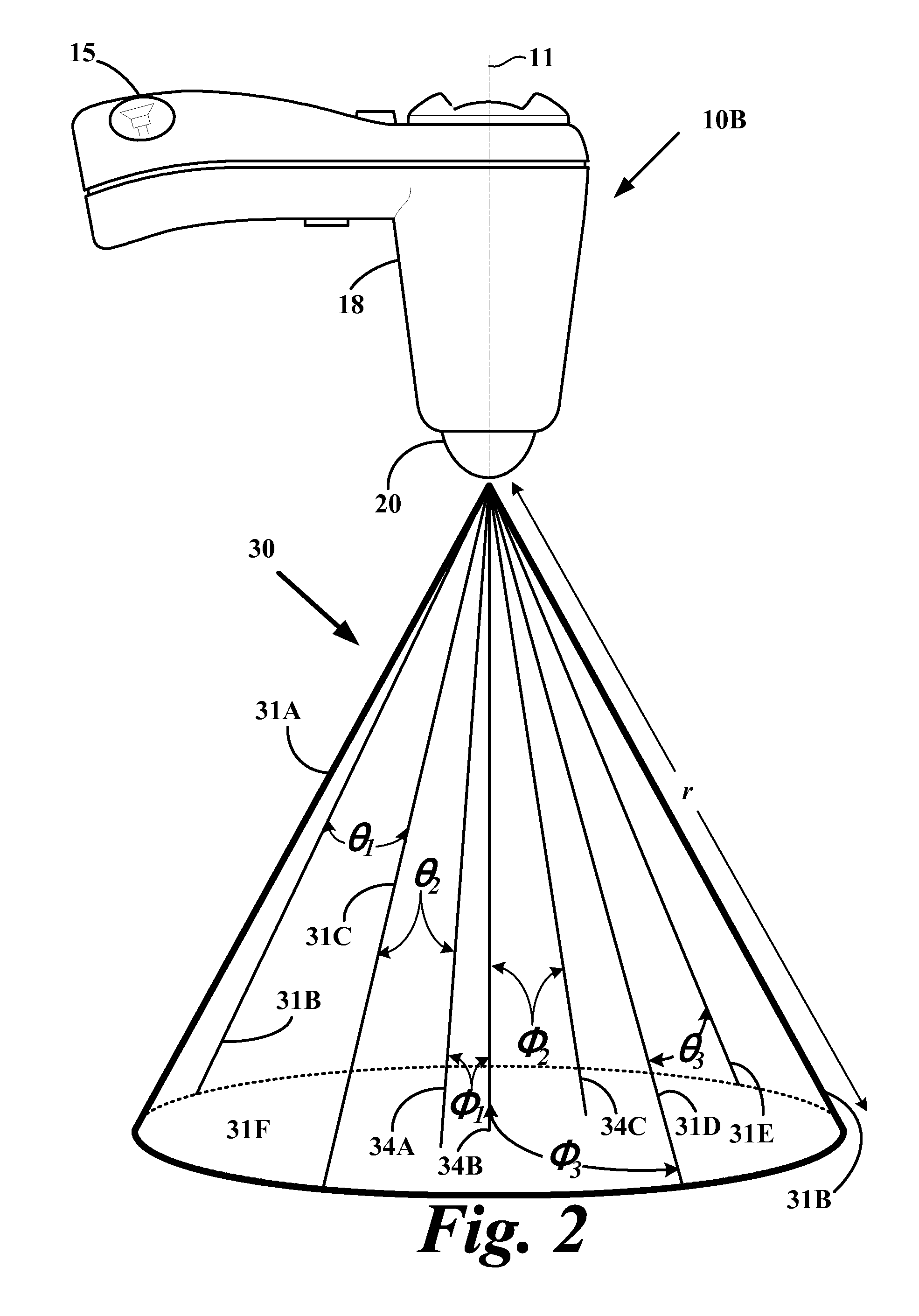
[0091]One preferred embodiment includes a three dimensional (3D) ultrasound-based hand-held 3D ultrasound device to acquire at least one 3D data set of a heart in order to measure a change in left ventricle volume at end-diastolic and end-systole time points as determined by an accompanying ECG device. The difference of left ventricle volumes at end-diastolic and end-systole time points is an ultrasound-based ventricular ejection fraction measurement.
[0092]A hand-held 3D ultrasound device is used to image a heart. A user places the device over a chest cavity, and initially acquires a 2D image to locate a heart. Once located, a 3D scan is acquired of a heart, preferably at ECG determined time points. A user acquires one or more 3D image data sets as an array of 2D images based upon the signals of an ultrasound echoes reflected from exterior and interior cardiac surfaces for each of an ECG-determined time points. 3D image data sets are stored, preferably in a device and / or transferred...
PUM
 Abstract
Description
Claims
Application Information