
Radio Frequency Ablation Electrode for Selected Tissue Removal

a radiofrequency ablation and electrode tip technology, applied in the field of radiofrequency electrodes, can solve the problems of inability to achieve therapeutic effects, lower back pain, lumbar pain, etc., and achieve the effect of convenient positioning of the electrode tip

Inactive Publication Date: 2008-10-09
KOREA UNIV IND & ACADEMIC CALLABORATION FOUND +1
View PDF14 Cites 146 Cited by
  • Summary
  • Abstract
  • Description
  • Claims
  • Application Information

AI Technical Summary

Benefits of technology

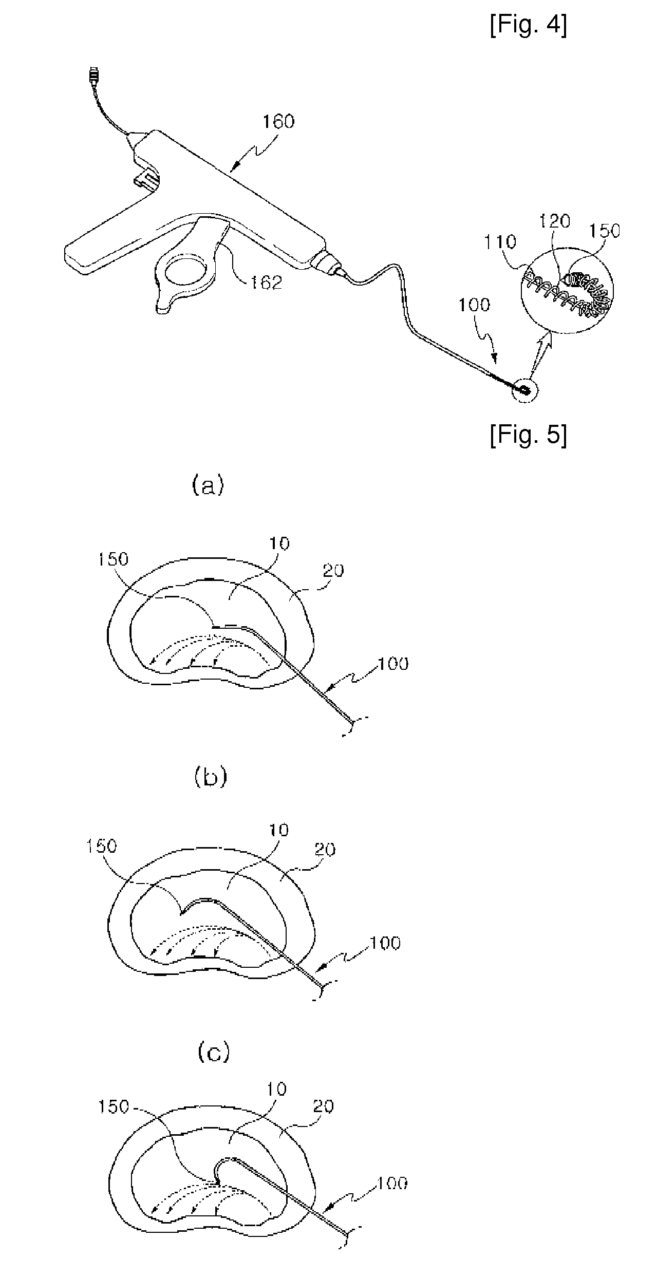
[0023]The radiofrequency electrode for selective ablation of a body tissue according to the present invention can be used for ablating a tissue in a body, by inserting, through a catheter, a radiofrequency electrode tip to a tissue, and then by controlling the direction and position of the electrode tip through pulling an electrode lead in the form a metal wire to modify the coil spring part, and thus easily positioning the electrode tip in a specific region.

Problems solved by technology

Generally, if a hernia of the intervertebral discs in the spine occurs, the inter-vertebral discs in the spine protrude to put pressure on an adjacent nerve, thus causing a lower back pain.
This phenomenon is referred to as a “hernia of the intervertebral discs.” The protruded parts of the intervertebral discs do not restore their original states and continuously maintain their protruded forms, whereby pressure is put on the nerve near the spin, thereby leading to a lumbar pain.
However, a therapeutic effect cannot be attained in 30% of the surgically operated patients, and further the surgical operation is accompanied by ablation of the spinal nerve region, which causes 5 to 10% of the operated patients to suffer Failed Back Surgery Syndromes (F.B.S.S) for one's lifetime.

Method used


Image

  • Radio Frequency Ablation Electrode for Selected Tissue Removal
  • Radio Frequency Ablation Electrode for Selected Tissue Removal
  • Radio Frequency Ablation Electrode for Selected Tissue Removal

Examples


Embodiment Construction

[0048]Hereinbelow, preferable Examples of the present invention will be described in detail with reference to the accompanying figures.

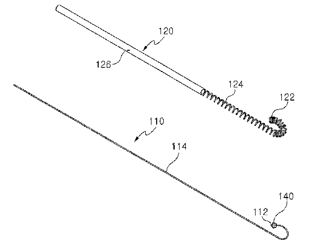
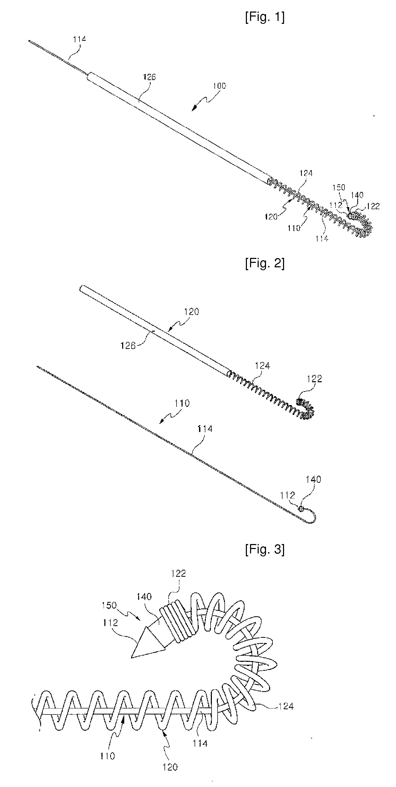
[0049]FIG. 1 is a perspective view of the radiofrequency electrode according to the first Example of the present invention, FIG. 2 is a perspective view of separation of an external electrode and an internal electrode of FIG. 1, and FIG. 3 is a detailed view of the end part of the radiofrequency electrode of FIG. 1. As illustrated in the figures, the radiofrequency electrode 100 of the first Example is configured such that the first electrode 110 in the form of a metal wire is inserted into the second electrode 120 having its end part in the form of a coil spring.

[0050]The first electrode 110 and the second electrode 120 are guided by a catheter 60 (illustrated in FIG. 8) and inserted into a body tissue.

[0051]The first electrode 110 is configured such that the first electrode lead 114 is inserted into the second electrode 120 and disposed therein, an...


PUM


Abstract

The present invention relates to a radiofrequency electrode for selective ablation of a body tissue, comprising a first electrode 110 and a second electrode 120 to be inserted, through a catheter 60, into the body tissue, wherein the first electrode tip 112 formed at the end of the first electrode 110 and the second electrode tip 122 formed at the end of the second electrode 120 are bonded at a predetermined interval. Specifically, a coil spring is bonded to the ends of the first electrode 110 and the second electrode 120, and the coil spring is configured to have its end part bent in the free state and be transformed by pulling either or both of the first electrode and the second electrode. By using the electrode, ablation of a desired tissue region in a body with radiofrequency by easily controlling the direction and the position of the electrode tip can be easily performed.

Description

TECHNICAL FIELD[0001]The present invention relates to a radiofrequency electrode for locally ablating a tissue in a specific region in a body using a radiofrequency (RF), and more specifically to a radiofrequency electrode which is used for easily ablating a tissue in a desired location, by inserting, through a catheter, a radiofrequency electrode tip assembly to a tissue region in a body to be ablated, and then controlling the direction of the electrode by an elastic force of an end part of the radiofrequency electrode.BACKGROUND ART[0002]Generally, if a hernia of the intervertebral discs in the spine occurs, the inter-vertebral discs in the spine protrude to put pressure on an adjacent nerve, thus causing a lower back pain. The intervertebral discs are composed of a nucleus pulposus 10 (illustrated in FIG. 8) and an annulus fibrosus surrounding the nucleus pulposus 20 (illustrated in FIG. 8). If upon applying any physical impact to the intervertebral discs, the inner wall of the a...

Claims


Application Information

Patent Timeline
Patent Type & Authority Applications(United States)
IPC IPC(8): A61B18/14
CPCA61B18/1492A61B2018/1435A61B2018/1425A61B2018/0044A61N1/05
Inventor LEE, SANG-HEONHWANG, CHANG-MOKIM, BYUNG-JOSUN, KYUNGHONG, JUNG-HWA
Owner KOREA UNIV IND & ACADEMIC CALLABORATION FOUND
Learn More