Methods and Instruments of Reducing a Fracture

a fracture and fixation method technology, applied in the field of orthopaedic instruments, can solve the problems of fracture reduction that is not stable or anatomically correct, non-union or malunion, etc., and achieve the effect of reducing the fracture, reducing the fracture, and reducing the fracture load

Inactive Publication Date: 2008-10-09
SMITH & NEPHEW INC
View PDF97 Cites 36 Cited by
  • Summary
  • Abstract
  • Description
  • Claims
  • Application Information

AI Technical Summary

Benefits of technology

[0013]The invention also relates to devices for treating femoral fractures. Femoral fractures are usually treated with the help of an intramedullary nail that is inserted into the canal of the femur to fixate the portions of the femur that are fractured. The invention provides a treatment for fracture fixation that allows the fracture to be reduced and loaded. The invention is a sliding compression orthopaedic implant. Sliding compression permits variations in loading of the fracture without compromising the anatomical reduction that is desired.
[0014]The method and instrumentation described herein provide the advantage of enabling a surgeon to reduce a fracture correctly before putting an implant into the body. Prior art implants attempt to achieve reduction with an implantable device that is placed into the body prior to reducing the fracture and often leads to a fracture reduction that is not stable or anatomically correct. These could lead to non-unions or mal-unions. The methods and instrumentation described herein also offers the advantage of being minimally invasive. Several methods also reduce the need for multiple holes to be drilled thereby avoiding the occurrence of stress risers.
[0016]Further, the invention is, briefly, a sliding compression orthopaedic implant. The implant includes a first implant member and a second implant member. The first implant member, such as an intramedullary nail or extramedullary plate, has a transverse hole, and the second implant member is associated with or connected to the transverse hole. The second implant member has a shank, and the shank has a bone engagement portion at a first end portion and a sliding compression member at a second end portion. The sliding compression orthopaedic implant maintains the reduction of the fracture but allows for dynamic loading to aid in fracture healing.

Problems solved by technology

Prior art implants attempt to achieve reduction with an implantable device that is placed into the body prior to reducing the fracture and often leads to a fracture reduction that is not stable or anatomically correct.
These could lead to non-unions or mal-unions.

Method used


Image

  • Methods and Instruments of Reducing a Fracture
  • Methods and Instruments of Reducing a Fracture
  • Methods and Instruments of Reducing a Fracture

Examples


Embodiment Construction

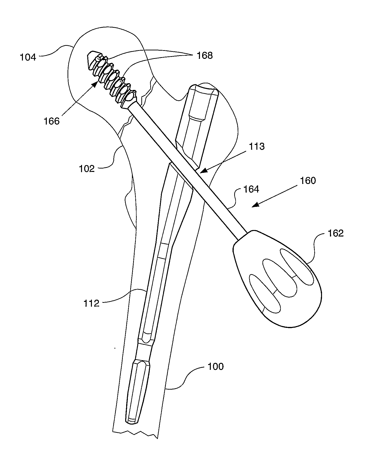
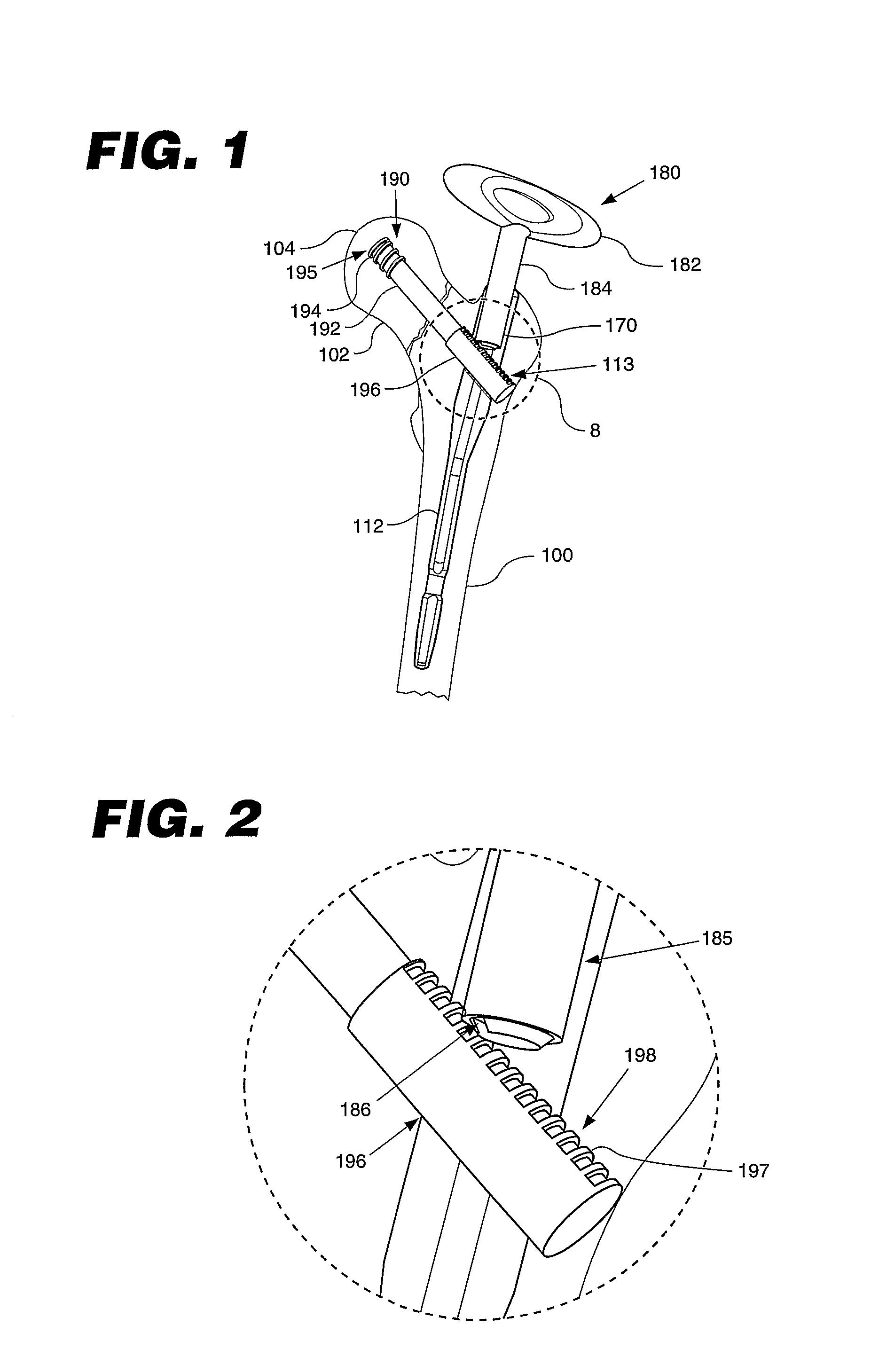
[0054]Referring to the accompanying drawings in which like reference numbers indicate like elements, FIGS. 1 and 2 illustrate a femur 100, a femoral neck 102, a femoral head 104, and a first instrument for reducing a fracture of a bone. In the depicted embodiment, the first instrument is used to reduce a fracture on a femoral neck of a femur. The first instrument includes an orthopaedic surgical implant 112, an implant member 190, and a driving member 180. In the embodiment depicted in FIG. 1, the orthopaedic surgical implant 112 is an intramedullary nail. The intramedullary nail 112 has a longitudinally extending bore 170 and a transverse hole 113. The implant member 190 is associated with or connected to the transverse hole 113. In the embodiment depicted in FIG. 1, the implant member 190 is slidingly engaged with the transverse hole 113. In some embodiments, the implant member 190 is cannulated to allow delivery of a material to the bone. The material may be a bone cement, a biol...


PUM


Abstract

An instrument for reduction of a bone fracture is disclosed. The instrument includes an orthopaedic surgical implant (112), an implant member (190, 200, 270), and a driving member (180, 210, 260). The implant member (190, 200, 270) has a bone engagement portion (195, 203, 275) and a driven portion (197, 208, 278). The driving member (180, 210, 260) cooperates with the driven portion (197, 208, 278) to move the implant member (190, 200, 270) and reduce the fracture. Also disclosed is a sliding compression orthopaedic implant (300). The implant (300) comprises a first implant member (310), said first implant member (310) having a transverse hole (311); and a second implant member (312) connected to said transverse hole (311), said second implant member (312) having a shank (314), and said shank (314) having a bone engagement portion (316) at a first end portion (318) and a sliding compression member (320) at a second end portion (322).

Description

CROSS-REFERENCE TO RELATED APPLICATIONS[0001]This application claims the benefit of U.S. Provisional Application No. 60 / 721,367, filed Sep. 28, 2005 and U.S. Provisional Application No. 60 / 721,369, filed Sep. 28, 2005. The disclosure of each application is incorporated by reference in its entirety.STATEMENT REGARDING FEDERALLY SPONSORED RESEARCH OF DEVELOPMENT[0002]Not Applicable.APPENDIX[0003]Not Applicable.BACKGROUND OF THE INVENTION[0004]1. Field of the Invention[0005]This invention relates generally to orthopaedic instrumentation and, more particularly, to internal fixation of a fracture.[0006]2. Related Art[0007]It is often desired to achieve reduction of a fracture prior to insertion of an implant into the fracture location. It is difficult to obtain an accurate reduction after an implant has been inserted. Further, it is difficult to accurately reduce a fracture with an implant.[0008]In addition to the problems of fracture reduction, there have also been problems in treating ...

Claims


Application Information

Patent Timeline
Patent Type & Authority Applications(United States)
IPC IPC(8): A61F5/04A61F5/00
CPCA61B17/7233A61B17/725A61B17/7258A61B17/744A61B17/746
Inventor EVANS, DAVID L.AUSTIN, GENE EDWARDGRUSIN, NATHANIEL KELLEYJANNA, SIED W.RAINS, JAMES K.GOSNEY, MARK S.RITCHEY, NICHOLAS S.FABER, HENRY B.LANDREM, KAMRIN R.
Owner SMITH & NEPHEW INC
Why Eureka
Try Eureka