Vehicle control system

Active Publication Date: 2008-10-09
DENSO CORP
View PDF32 Cites 33 Cited by
  • Summary
  • Abstract
  • Description
  • Claims
  • Application Information

AI Technical Summary

Benefits of technology

[0007]The present invention has therefore an object to provide a vehicle control system which is capable of suppressing vibrations that occur at various portions of a vehicle by a vehicle vibration model that enables the vibration state

Problems solved by technology

However, when the suspension vibration model and the tire vibration model are separated from each other, the vibration state in the longitudinal (front-back) direction of the tire cannot be estimated with a high precision.
However, when th

Method used


Image

  • Vehicle control system
  • Vehicle control system
  • Vehicle control system

Examples


Embodiment Construction

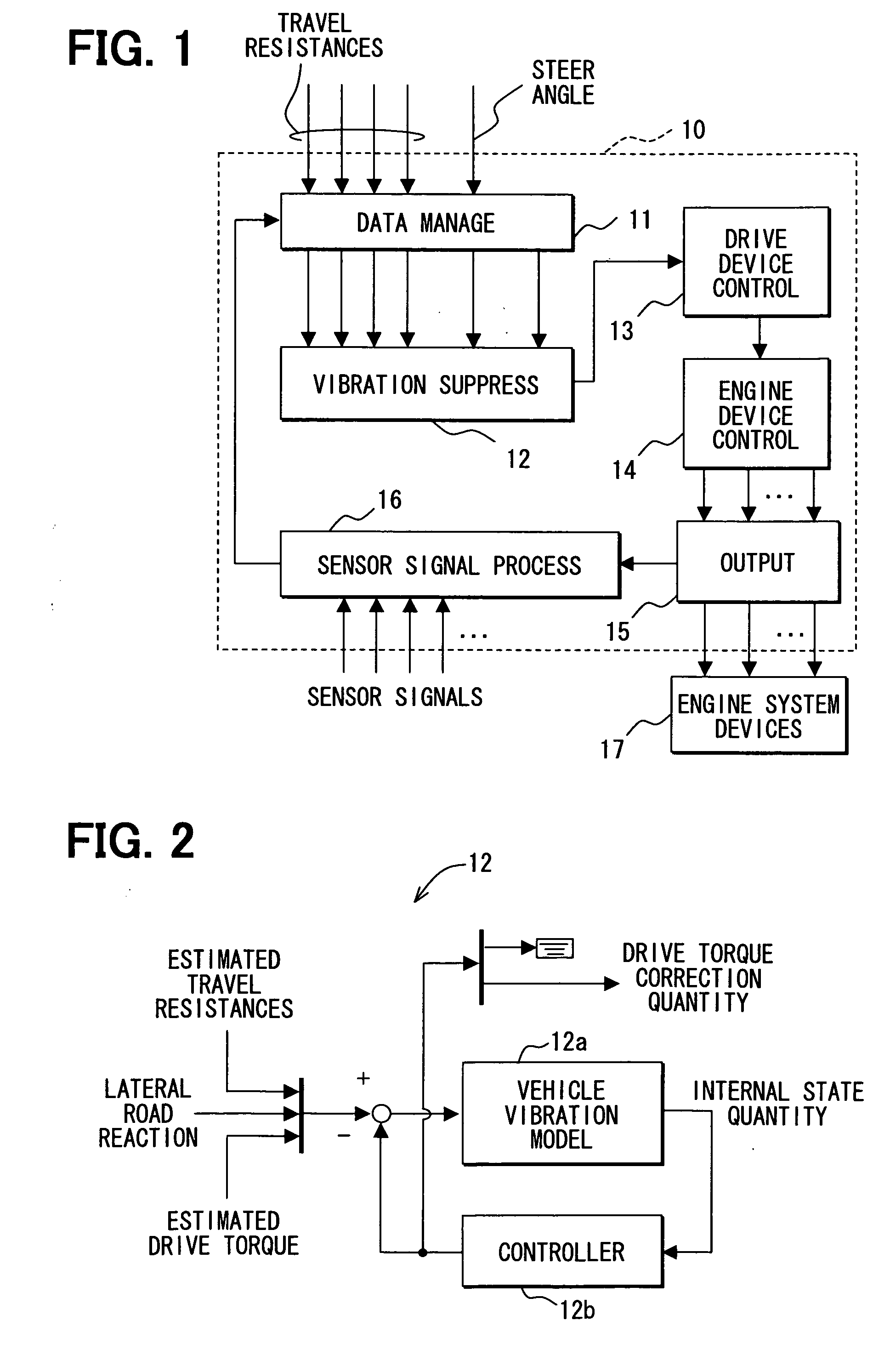
[0033]Referring to FIG. 1, a vehicle control system is mainly made up of a control device (engine / drive system ECU) 10 of an engine and drive system (engine / drive system). The engine / drive system ECU 10 communicates with another ECU such as a brake system ECU and a power steering ECU (not shown) on an in-vehicle LAN (not shown), which is a communication network disposed within a vehicle.

[0034]The engine / drive system ECU 10 includes a data management unit 11. The data management unit 11 includes a communication interface function that manages a transmit / receive of data using the above in-vehicle LAN. The data management unit 11 also includes a calculation function that calculates an estimated drive torque which is an input parameter necessary for simulating the vibrations that occur in an actual vehicle in a vehicle vibration model that will be described later, based on various sensor signals that are loaded through a sensor input signal processing unit 16.

[0035]More specifically, th...


PUM


Abstract

A vehicle control system estimates the vibration states of tires by using a vehicle vibration model that is separated into a vehicle body vibration model, a chassis vibration model, and a tire vibration model with high precision. The tire vibration model in the vehicle vibration model is formed of a rear wheel tire vibration model, a front wheel tire vibration model, and a virtual coupling element vibration model that virtually couples the rear wheel tire vibration model and the front wheel tire vibration model. Influence of the vibration state that is conducted between the front wheel tires and the rear wheel tires is considered while the tire vibration model and the chassis vibration model are separated from each other, thereby making it possible to estimate the vibrations that occur in the front wheel tires and the rear wheel tires.

Description

CROSS REFERENCE TO RELATED APPLICATION[0001]This application is based on and incorporates herein by reference Japanese Patent Application No. 2007-97792 filed on Apr. 3, 2007.FIELD OF THE INVENTION[0002]The present invention relates to a vehicle control system that suppresses vibrations which occur at various portions of a vehicle.BACKGROUND OF THE INVENTION[0003]US 2005 / 0049761 (JP 2004168148A) discloses a vehicle control system that is capable of suppressing the vibrations of a vehicle body. The vehicle control system corrects an input instruction so as to suppress the vibrations of the vehicle by a motion model. The motion model is formed by a dynamic model of the vibrations of tires of the vehicle, the vehicle body unsprung vibrations in suspensions, and the vehicle body sprung vibration which are received by the vehicle body per se, which occurs according to an input instruction corresponding to at least one of accelerator operation, steering operation, and brake operation whic...

Claims


Application Information

Patent Timeline
IPC IPC(8): G06F17/00B60L3/00B60T8/00B60W10/04B60W10/06B60W10/08B60W10/18B60W10/184B60W30/00B60W30/20B60W40/10B60W40/11B60W40/114B60W40/12G01M17/007
CPCB60T8/173B60T2260/08B60T2270/86B60W10/06B60W10/08B60W10/184B60W30/025B60W30/04B60W30/20B60W2050/0036F16F15/02B60C99/006
Inventor MATSUMOTO, TOSHIKISAWADA, MAMORU
Owner DENSO CORP
Why Eureka
Try Eureka