Program Counter (PC) Trace

a program counter and trace technology, applied in the field of integrated circuits, can solve the problem of increasing the number of pcs per clock cycl

Inactive Publication Date: 2008-10-09
APPLE INC
View PDF20 Cites 57 Cited by
  • Summary
  • Abstract
  • Description
  • Claims
  • Application Information

AI Technical Summary

Benefits of technology

[0009]In another embodiment, an integrated circuit comprises a first processor configured to output PC trace records, wherein the PC trace records provide data indicating the PCs of instructions retired by the first processor. Additionally, the PC trace records comprise control records and data records, and a given data record is associated with a given control record. An order of the given data record and the given control record in the PC trace records is arbitrary for at least some control records and corresponding data records. That is, either the given control record or its given data record may appear first in the trace. A trace unit is coupled to receive the plurality of PC trace records, wherein the trace unit comprises a trace memory into which the trace unit is configured to store the plurality of PC trace records.

Problems solved by technology

Additionally, as the complexity of the processor and / or the integrated circuit including the processor increases (superscalar design, multiple cores per chip, etc.), the number of PCs per clock cycle increases.

Method used


Image

  • Program Counter (PC) Trace
  • Program Counter (PC) Trace
  • Program Counter (PC) Trace

Examples


Embodiment Construction

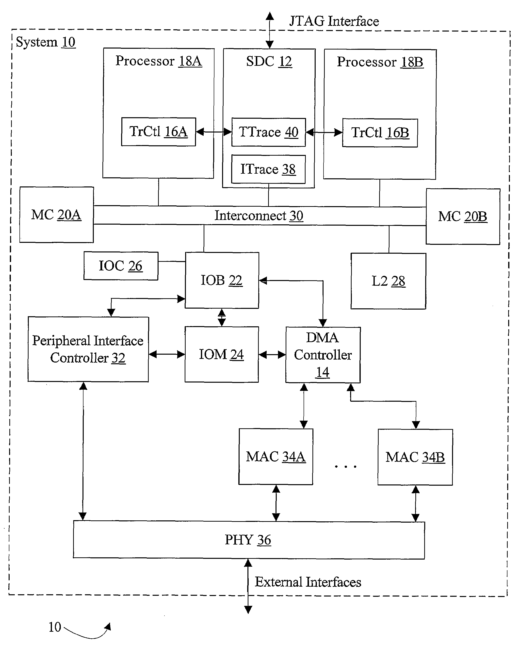
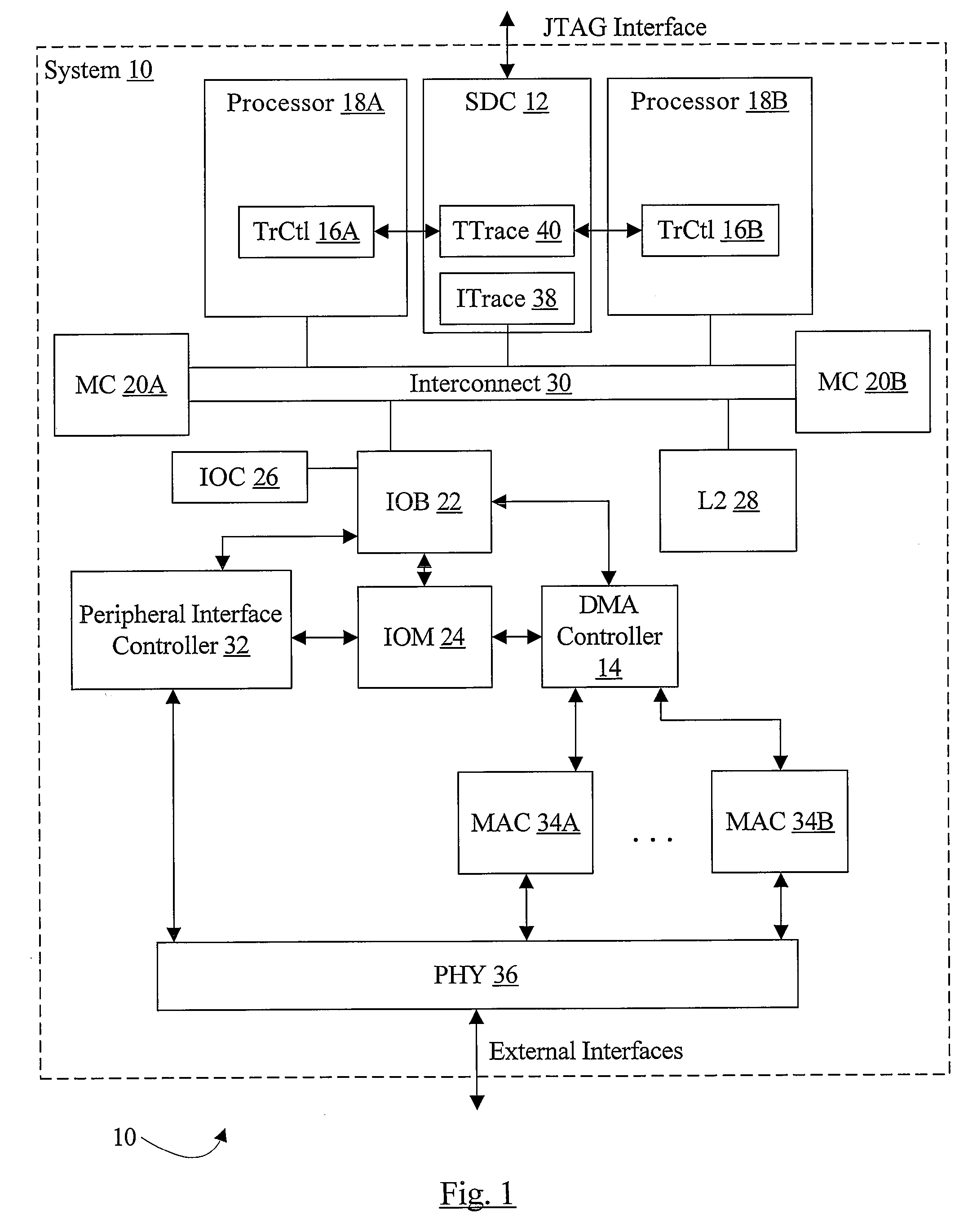
[0025]Turning now to FIG. 1, a block diagram of one embodiment of a system 10 is shown. In the illustrated embodiment, the system 10 includes a system debug controller (SDC) 12, a DMA controller 14, one or more processors such as processors 18A-18B, one or more memory controllers such as memory controllers 20A-20B, an I / O bridge (IOB) 22, an I / O memory (IOM) 24, an I / O cache (IOC) 26, a level 2 (L2) cache 28, an interconnect 30, a peripheral interface controller 32 and one or more media access control circuits (MACs) such as MACs 34A-34B, and a physical interface layer (PHY) 36.

[0026]The SDC 12, the processors 18A-18B, memory controllers 20A-20B, IOB 22, and L2 cache 28 are coupled to the interconnect 30. The IOB 22 is further coupled to the IOC 26 and the IOM 24. The DMA controller 14 is also coupled to the IOB 22 and the IOM 24. The MACs 34A-34B are coupled to the DMA controller 14 and to the physical interface layer 36. The peripheral interface controller 32 is also coupled to th...


PUM


Abstract

In one embodiment, an integrated circuit comprises a first processor configured to output program counter (PC) trace records, wherein PC trace records provide data indicating the PCs of instructions retired by the first processor. The integrated circuit further comprises a second source of trace records, and a trace unit coupled to receive the PC trace records from the first processor and the trace records from the second source. The trace unit comprises a trace memory into which the trace unit is configured to store the PC trace records and trace records from the second source. The trace unit is configured to interleave the PC trace records and the trace records from the second source in the trace memory according to the order of receipt of the records.

Description

BACKGROUND[0001]1. Field of the Invention[0002]This invention is related to the field of integrated circuits that include processors, and more particularly to generating program counter (PC) traces in such integrated circuits.[0003]2. Description of the Related Art[0004]Electronic systems of various types include processors, also referred to as central processing units (CPUs). A processor can include multiple integrated circuit “chips”. The so-called microprocessor is typically a processor on a single chip, with no other “non-processor” functionality. More recently, processors have been integrated with other functionality in devices commonly referred to as integrated processors, embedded processors, and system on a chip (SOC) devices.[0005]The processors execute programs, and can interact with other devices in the system under control of the program being executed. The program comprises one or more instruction sequences, which can include branches within the sequences, branches to o...

Claims


Application Information

Patent Timeline
Patent Type & Authority Applications(United States)
IPC IPC(8): G06F11/34
CPCG06F11/3476G06F11/3636
Inventor WALKER, KEVIN R.MYLIUS, JOHN H.
Owner APPLE INC
Why Eureka
Try Eureka