Helmet With Visor

a technology of visor and visor body, which is applied in the field of helmets with visors, can solve the problems of difficult integral and firmly the cap body to each other, the visor is easily peeled off from the cap body, and the conventional configuration, so as to increase the joining area, strengthen the joining of the visor, and increase the joining area

Inactive Publication Date: 2008-10-16
MIDORI ANZEN
View PDF5 Cites 15 Cited by
  • Summary
  • Abstract
  • Description
  • Claims
  • Application Information

AI Technical Summary

Benefits of technology

[0020]According to the present invention, as the joining portion of the visor and the cap body is annular in shape, it is possible to increase a joining area, and to strengthen the joining of the visor and the cap body. As the joining portion of the visor and the cap body is formed into the annular shapes to increase the joining area, the joining portion of the visor and the cap body can be formed into relatively simple shapes thereby facilitating the joining.
[0021]According to the present invention, as the microprojected part of the joining surface of the visor is fused to integrate the visor and the cap body, a configuration is similar to that when the visor is preliminarily injection-molded with the cap body, thereby increasing joining strength. Even when deformation occurs in the joining portion, the visor is never peeled off from the cap body.

Problems solved by technology

Accordingly, even when the front end of the flowing resin during the injection-molding of the cap body comes into contact with a joining surface of the ends of the visor set as an insert in the mold, it is difficult to integrally and firmly joint the visor and the cap body to each other by sufficiently fusing the joining surface of the visor.
Thus, the conventional configuration has problems as follows.
That is, when there is a tendency that an external force is applied to the visor to concentrate stress in the joining portion of the visor and the cap body thereby causing deformation, the visor is easily peeled off from the cap body.
As it is necessary in configuration to form the locking part, the locking hole or the like in the mold for injection-molding the visor, the configuration of the mold becomes complex.

Method used


Image

  • Helmet With Visor
  • Helmet With Visor
  • Helmet With Visor

Examples


Embodiment Construction

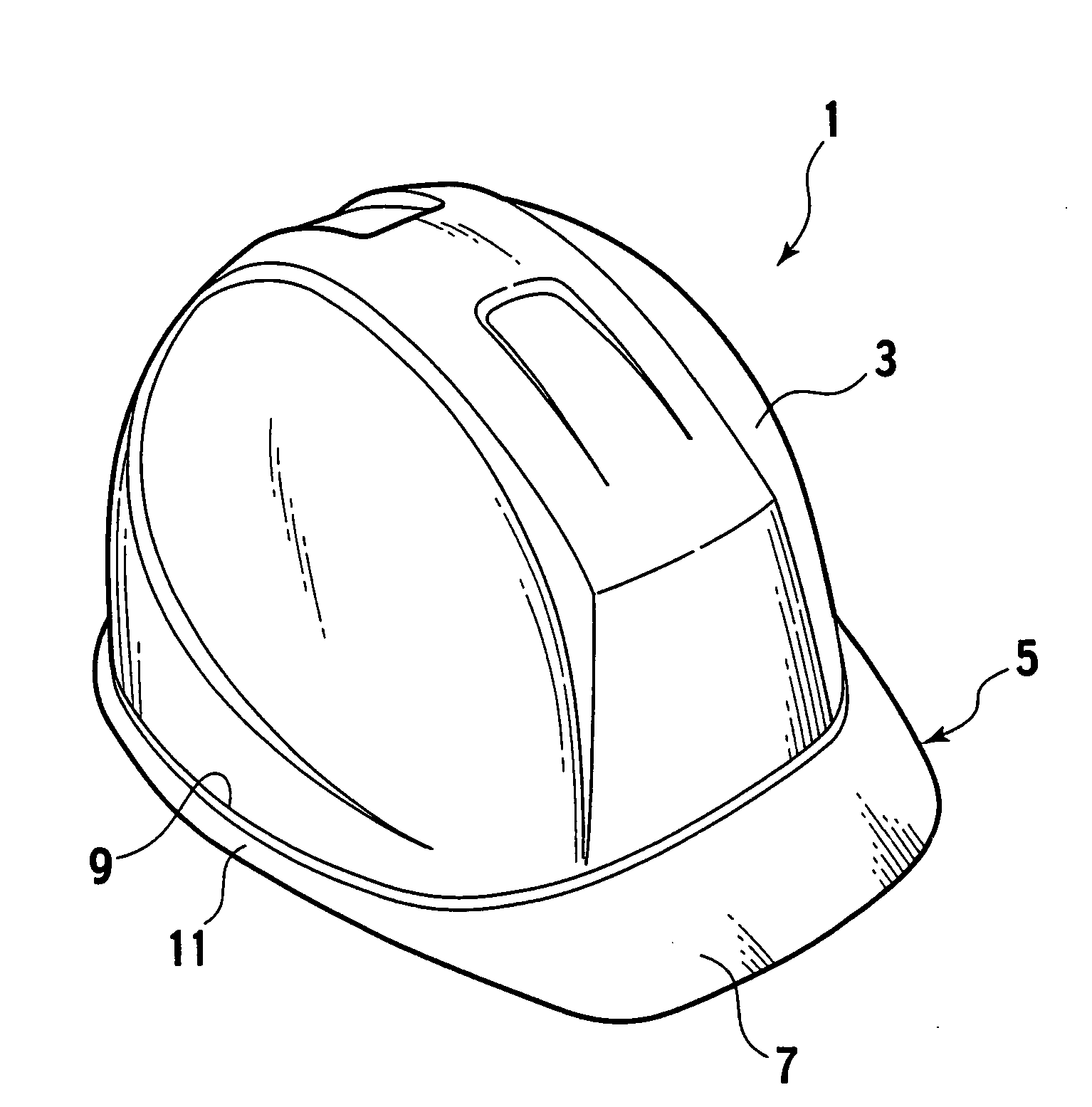
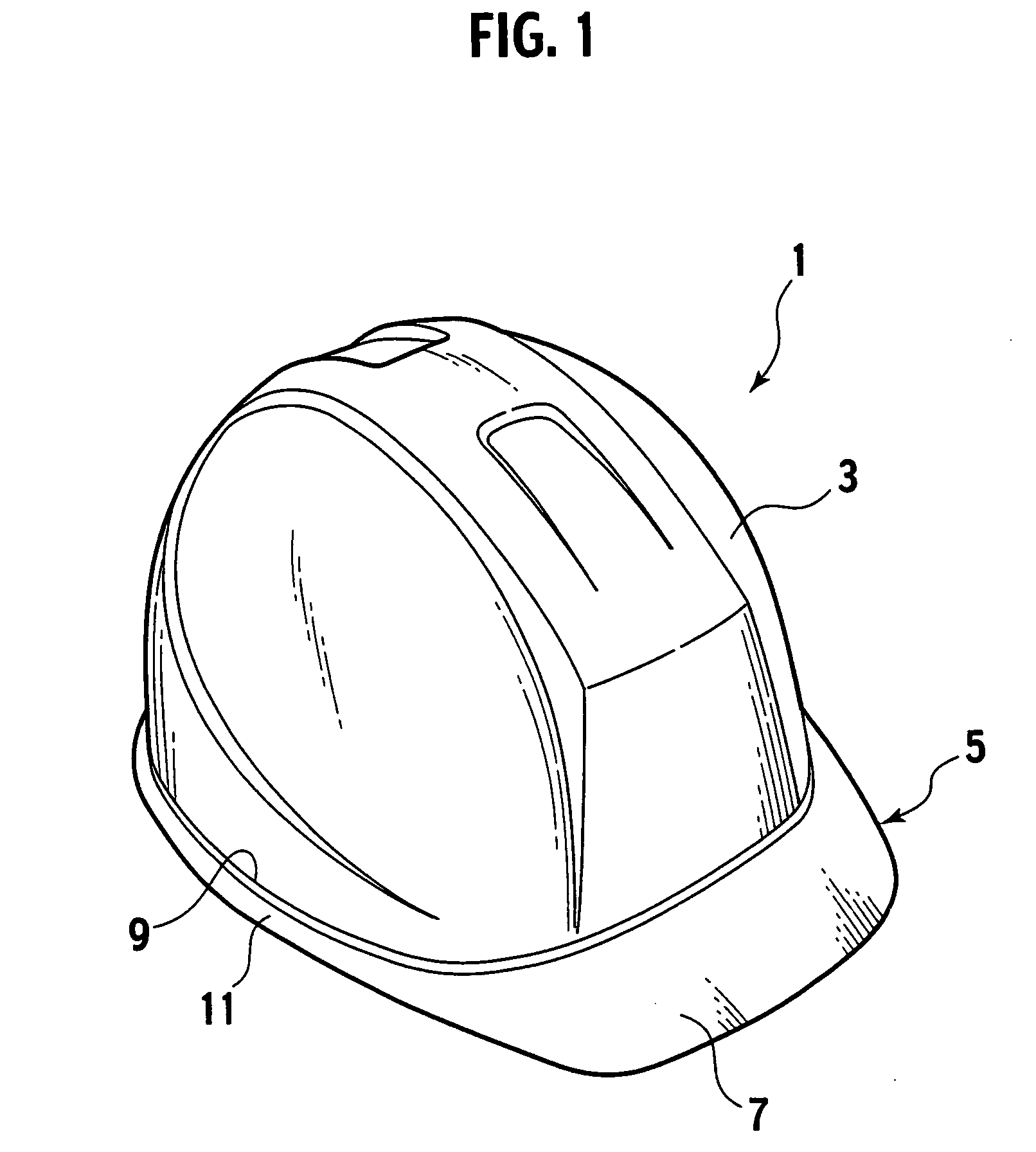
[0033]As shown in FIG. 1, a helmet 1 of an embodiment of the present invention includes a cap body 3 to be put on a head, and this cap body 3 integrally includes a flange-shaped visor 5. For example, the cap body 3 and the visor 5 are made of proper resins such as polycarbonate, and formed to be thin with approximately equal thicknesses. The visor 5 is formed to be transparent. It should be noted that the visor 5 is not always transparent.

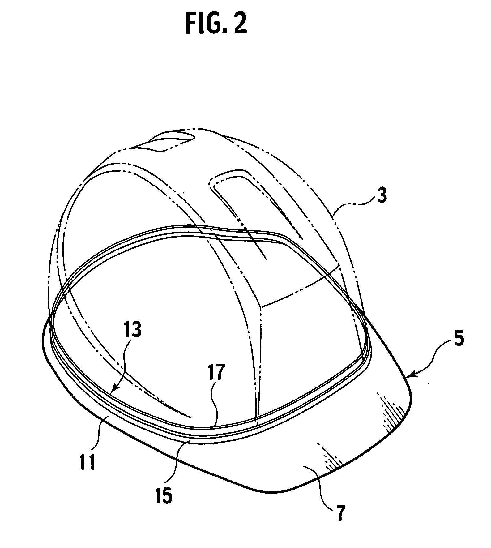
[0034]The visor 5 includes a wide flange part 7, and a belt-shaped annular portion 11 disposed in a rear part of the flange part 7 corresponding to a size of an opening end edge 9 of the cap body 3. The visor 5 includes an annular joining portion 13 (refer to FIGS. 2 and 3) integrally joined to an inner side of the opening end edge 9 of the cap body on the annular portion 11.

[0035]The joining portion 13 includes an annular wall 15 formed to project upward from the upper part of the annular portion 11. Inside the upper part of this annular wall 15, ...


PUM

PropertyMeasurementUnit
stress concentrationaaaaaaaaaa
thickaaaaaaaaaa

Abstract

A helmet 1 with a visor formed by integrally joining the preliminarily injection-molded visor 5 to a cap body 3, wherein an opening end edge 9 formed on the cap body is joined to the outer side of a joining wall 17 formed on the visor 5, and the joining wall 17 is held by the opening end edge 9 and a tongue-shaped part 31 formed on the inside of the cap body 3. The joined faces of the visor 5 and the cap body 3 are joined to each other by fusing, an intruding engagement part intruded in a through hole 22 formed in the joining wall 17 is formed at the opening end edge of the cap body 3, and the joining portion of the visor and the cap body is formed in annular shapes.

Description

TECHNICAL FIELD[0001]The present invention relates to a helmet with a visor. More specifically, the present invention relates to a helmet with a visor formed by integrally joining a preliminarily injection-molded thin resin molded article such as a visor to a cap body as a resin injection-molded article of the helmet when the cap body is injection-molded.BACKGROUND ART[0002]For a helmet with a visor used as a safety cap at, e.g., a building site, a civil engineering construction site, or the like, to widen an upper visual field, a helmet with a transparent visor has been proposed (e.g., Japanese Patent Publication No. 298469: see Patent Document 1).[0003]In the helmet 100 with a visor disclosed in the Patent Document 1, as shown in FIG. 11, a transparent visor 102 is integrally joined to a front bottom of a cap body 101. To increase strength of a joining portion of the cap body 101 and the visor 102, a plurality of engagement pieces 103 are formed in the joining portion of the visor...

Claims


Application Information

Patent Timeline
Patent Type & Authority Applications(United States)
IPC IPC(8): A42B3/22A41B3/06A42B3/04A42B3/18A42B3/32A42C2/00B29C45/14B29C65/02B29C65/56
CPCA42B3/227A42C2/00B29C37/0082B29C45/1657B29C2045/1659B29C2045/166B29L2031/4821
Inventor WATABIKI, HIROAKIUENO, HIROSHIHIRATSUKA, HEISABURO
Owner MIDORI ANZEN
Why Eureka
Try Eureka