Streamlined Counterbalanced Fishing Jig

Inactive Publication Date: 2008-10-16
KRUEGER GEORGE RAYMOND
View PDF99 Cites 19 Cited by
  • Summary
  • Abstract
  • Description
  • Claims
  • Application Information

AI Technical Summary

Benefits of technology

[0021](g) provide a lure which can be used effectively with a greater variety of live bait;
[0022](h) provide a lure with a body and hook configuration which will assure the greatest incidence of hook point embedment into the upper part of the fish mouth;
[0023](i) provide a lure with minimum amount of weight required to achieve proper presentation;
[0024](j) provide a

Problems solved by technology

Unfortunately, with the majority of jigs available today, this desired upright position is often difficult, if not impossible, to consistently maintain.
Improperly balanced jigs or jigs which incorporate planing surfaces or bulbous appendages to impart special desired actions to the lure often perform erratically and will tumble, rotate or spiral about the line axis which, in turn, result in twisted lines and improper lure presentation.
The results of improper presentation are hook embedment in areas other than the fish's upper jaw increasing the probability of injuring the fish, difficult hook removal and increased incidents of snagging on underwater obstacles.
During casting, retrieving, trolling or allowing the lure to sink on a slack line, external forces acting upon the jig body are introduced which upset this equilibrium resulting in the lures rotating about the line axis which, in turn, resul

Method used


Image

  • Streamlined Counterbalanced Fishing Jig
  • Streamlined Counterbalanced Fishing Jig
  • Streamlined Counterbalanced Fishing Jig

Examples


Embodiment Construction

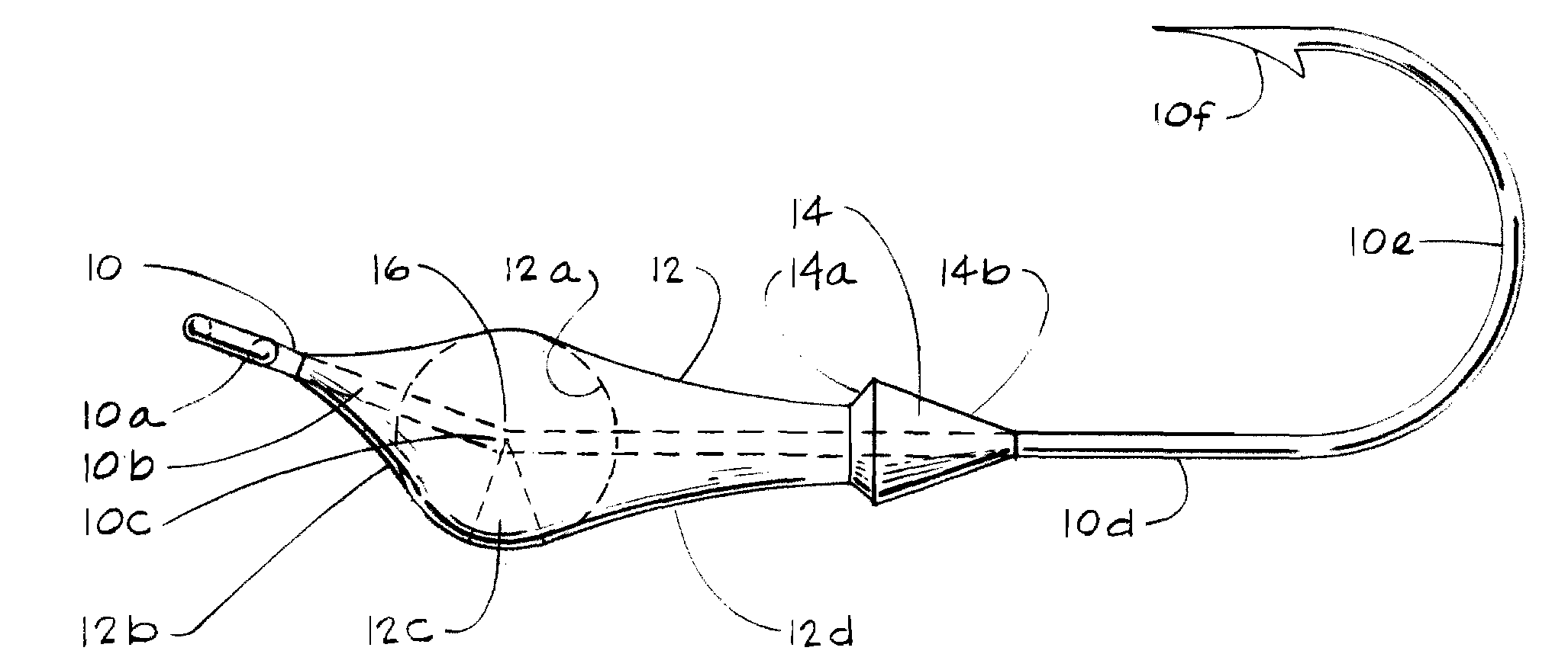
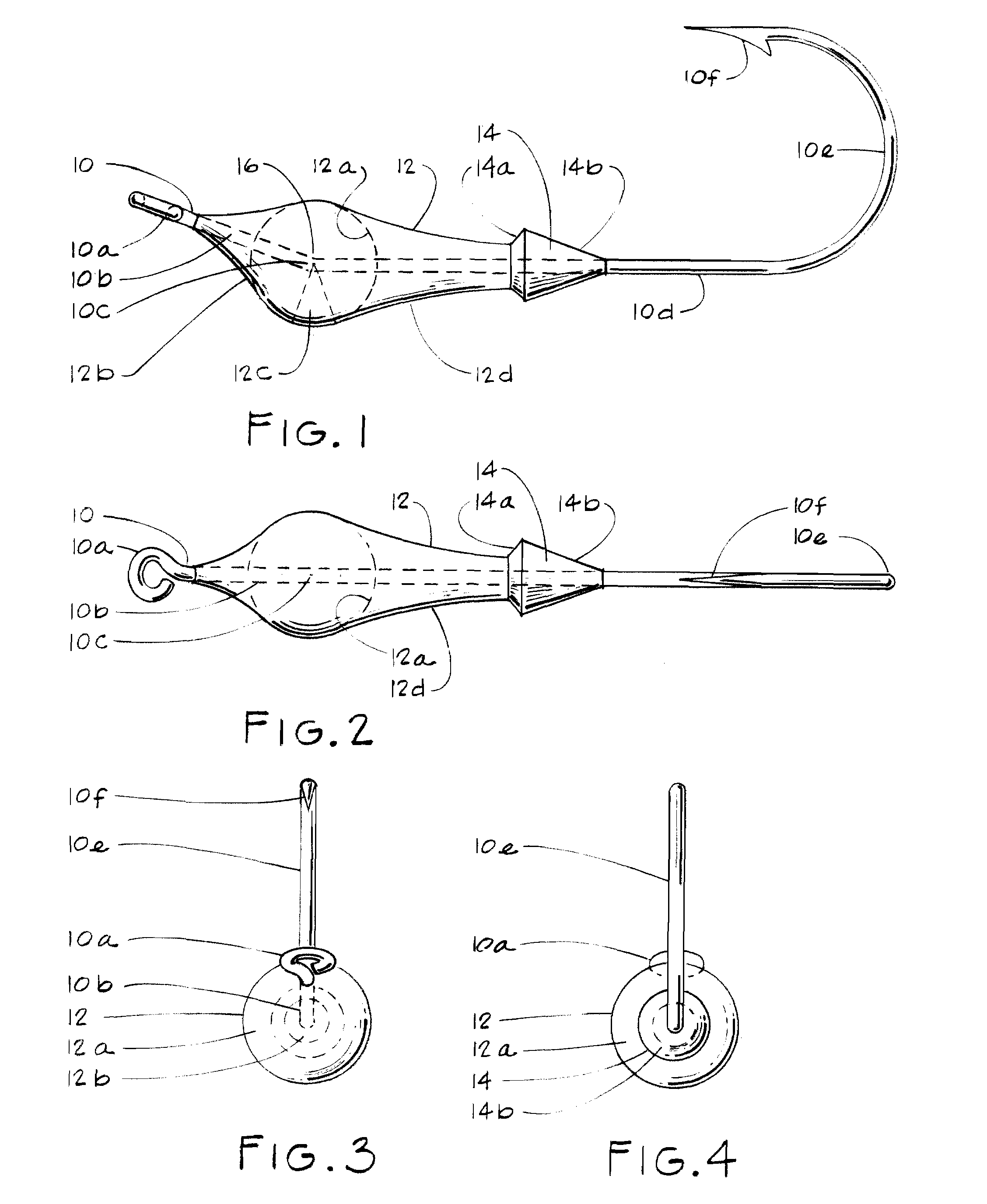
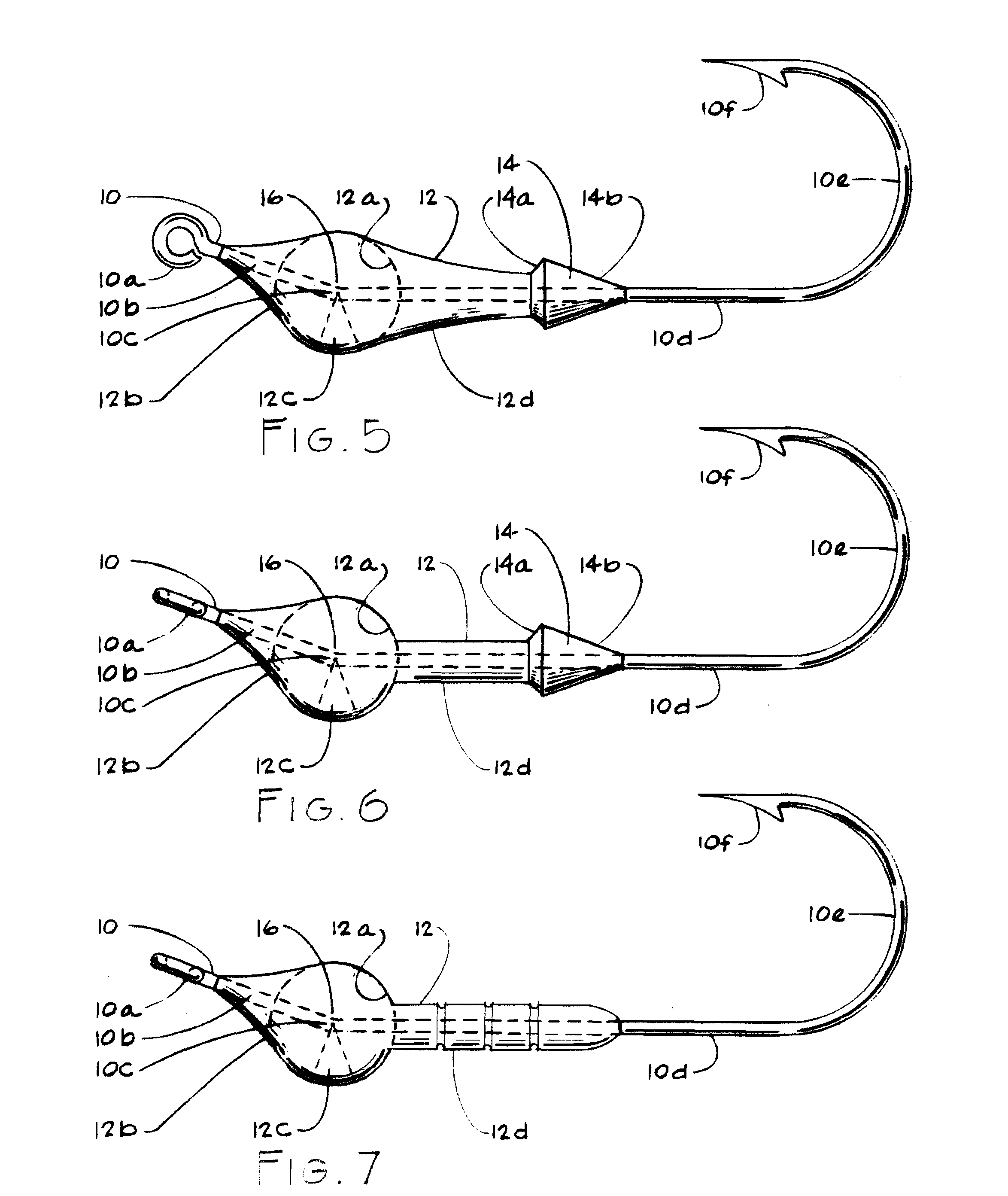
LIST OF DRAWING REFERENCE NUMBERS 8Fishing jig10hook10ahook eye10beye bend10ceye bend radius point10dhook shank10ehook curve10fhook point12metal body12aspherical body mass12bfrontal area (concaved)12ccounterbalancing weight wedge12dshank collar (concaved)14bait collar14abait collar rim14bconical portion of the bait collar16center of gravity

[0046]A preferred embodiment of the fishing jig 8 is illustrated in FIGS. 1-4 and shows a fish hook 10 with a metal body 12 cast about the hook 10. The hook 10 is a light Aberdeen ringed hook with an eye 10a adapted to be attached to a fishing line, and a short section attached to the eye 10a and referred to as the eye bend 10b. The eye bend 10b is bent towards the hook point 10f of a hook curve 10e at an angle of approximately 20° to a straight hook shank 10d. The eye 10a forms a leading extremity of the jig 8, while the hook curve 10e forms a trailing extremity. The hook point 10f may be barbed or barbless. An eye bend radius point 10c is locate...


PUM


Abstract

A fishing jig includes a fish hook integral construction with a center axis having a hook curve trailing extremity with a hook point, and a straight hook shank extending forwardly from the hook curve. An eye bend extends forwardly and upwardly at an eye bend radius point at an angle of substantially 20° relative to the axis of the hook shank, and terminating in a line-attachment eye leading extremity. A weighted metal body is connected to and distributed symmetrically along the hook shank and the eye bend. The body has a mass distribution which is greater below the center axis of the hook than above the center axis of the hook by creating a wedge on a lower portion of the body that counterbalances weight of the hook curve and the hook point. A center of gravity is defined above the wedge at substantially the eye bend radius point such that the jig assumes an upright position in which the hook shank is maintained and has a substantially horizontal attitude. The hook point lies in an uppermost position relative to the hook shank such that the jig will not tumble, spiral or rotate when attached on a fishing line.

Description

FIELD OF THE INVENTION[0001]This invention relates generally to metal-weighted fishing hooks commonly referred to as jigs.BACKGROUND OF THE INVENTION[0002]Jigs are hooks with metal weight attached directly to the shank of the hook to provide the weight necessary to cast the lure.[0003]Jigs have been used by anglers for many years, however, the introduction of light weight spinning reels, ultra sensitive rods and fine diameter lines offer a number of advantages as to how anglers fish jigs today.[0004]Reels allow greater casting distances with lighter lures and a greater range of retrieval speeds. Ultra sensitive rods allow the angler to feel the lightest fish strikes or structure that the lure is being retrieved through. Ultra light fine diameter lines produce less line drag allowing longer casting distances and faster descent rates when the lure is in the water.[0005]The advantage of the jig is its versatility. Its compact size to weight ratio provides a lure that casts easily. With...

Claims


Application Information

Patent Timeline
IPC IPC(8): A01K85/00
CPCA01K85/00
Inventor KRUEGER, GEORGE RAYMOND
Owner KRUEGER GEORGE RAYMOND
Why Eureka
Try Eureka