Oil sealing ring

Inactive Publication Date: 2008-10-16
YU XIUMING
View PDF0 Cites 20 Cited by
  • Summary
  • Abstract
  • Description
  • Claims
  • Application Information

AI Technical Summary

Benefits of technology

[0032]Since the oil sealing ring of the invention employs the axially-traversed trough disposed on the inner circumferential surface to the left of the split of the base ring, the radially-traversed upper groove disposed on the upper surface (including part of the flange) to the left of the split of the base ring, the outer radial lapping segment and the outer axial-radial lapping segment disposed to the left of the base ring, the axially-traversed outer groove disposed on the outer circumferential surface to the right of the base ring, a groove disposed on the outer circumferential surface to the right of the axially-traversed outer-groove t

Problems solved by technology

However, a problem with above-mentioned oil rings is tha

Method used


Image

  • Oil sealing ring
  • Oil sealing ring
  • Oil sealing ring

Examples


first embodiment

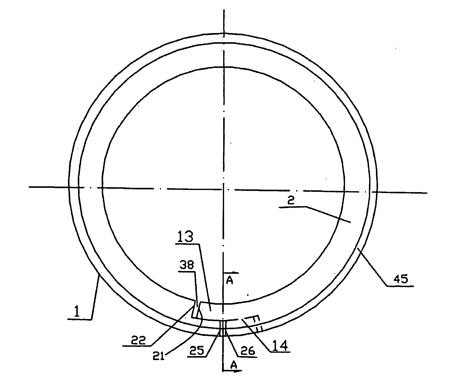
[0096]FIGS. 1-5 illustrate an oil sealing ring of the invention.

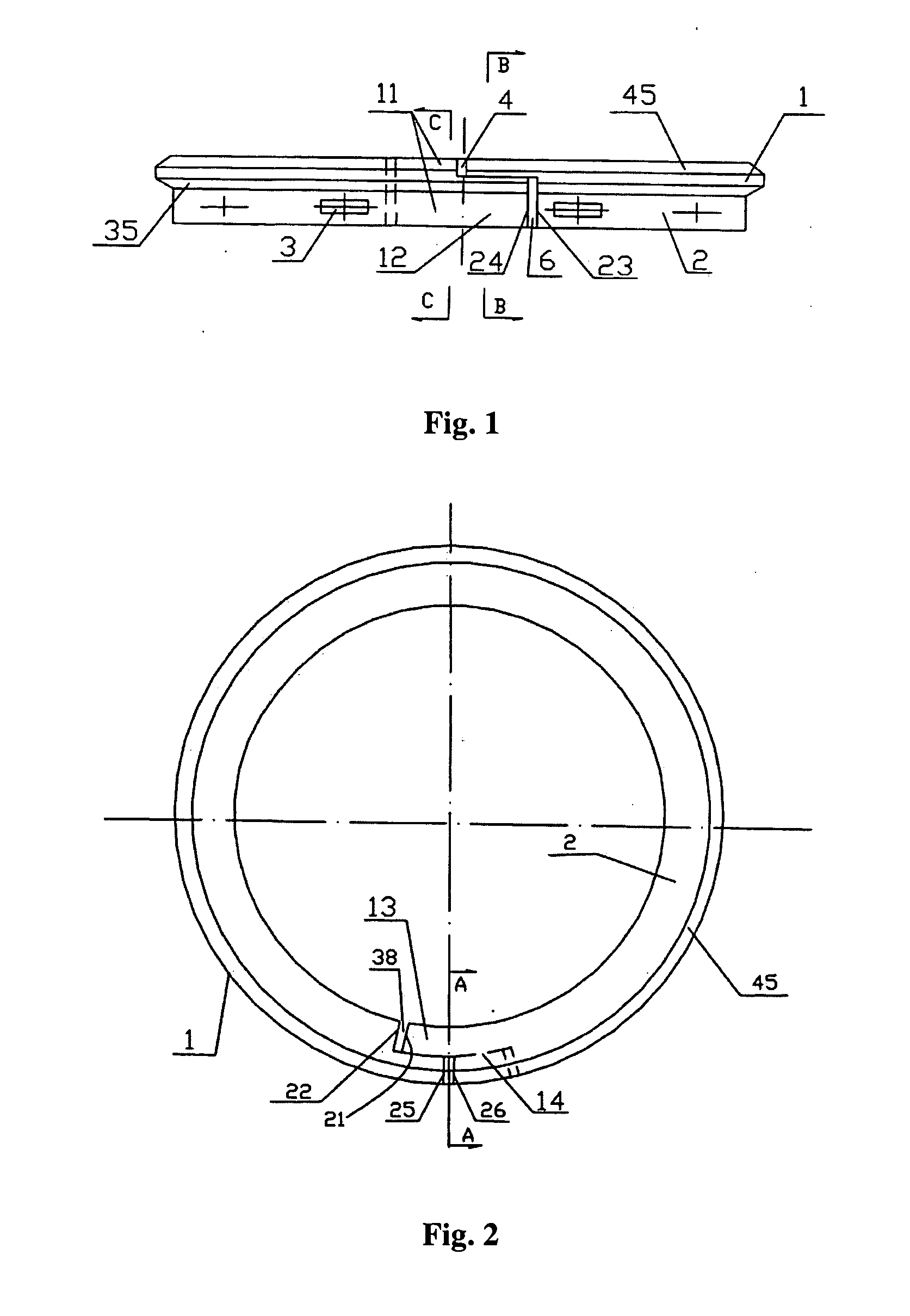
[0097]FIG. 1 shows a front view of a base ring 2 of an oil sealing ring according to a first embodiment of the invention. FIG. 2 shows a top view of an oil sealing ring according to a first embodiment of the invention. As shown in FIG. 2, the oil sealing ring of the invention comprises a base ring 2 having a split, and an annular flange 1 radially-protruding outwards is disposed on an outer circumferential surface of the base ring 2. A central axis of the outer circumferential surface of the flange 1 coincides with that of the outer circumferential surface of the base ring 2. A chamfer 45 is disposed at a junction between upper surface of the annular flange 1 and the outer circumferential surface thereof, and a lower outer-chamber 35 is disposed at a junction between lower surface of the annular flange 1 and the outer circumferential surface thereof. This reduces axial height of the annular flange 1 and the area of the ...

second embodiment

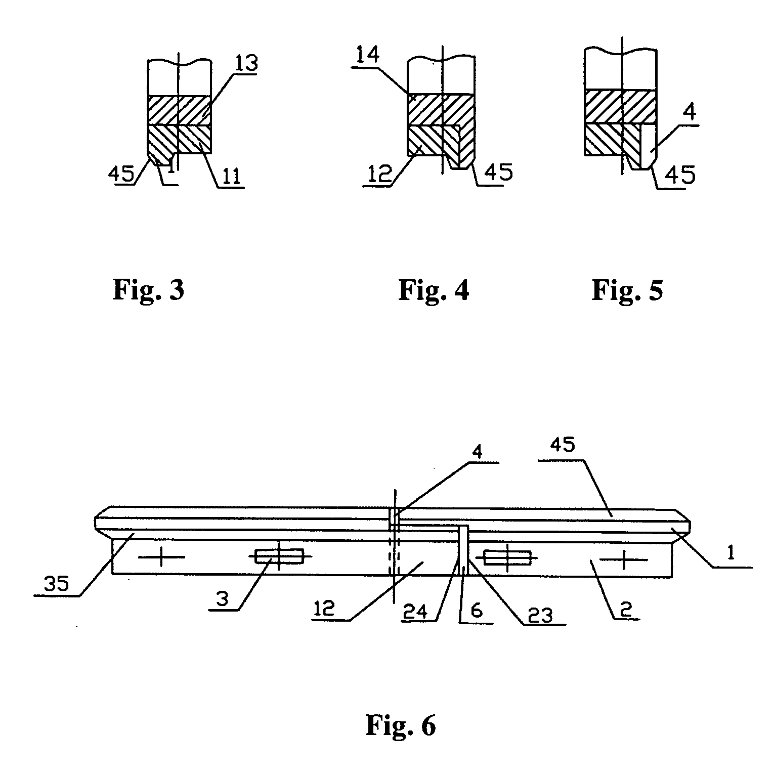
[0102]FIGS. 6-12 illustrate an oil sealing ring of the invention.

[0103]FIG. 6 is a front view of the base ring 2 of an oil sealing ring according to a second embodiment of the invention. FIG. 7 is a top view of an oil sealing ring according to a second embodiment of the invention. As shown in FIG. 7, an axially-traversed trough 5 is disposed on inner circumferential surface to the left of the split of the base ring 2. A radially-traversed upper groove 4 is disposed on the upper surface to the left of the split of the base ring 2. A lower bottom surface of the radially-traversed upper groove 4 is disposed in a position that is at half axial height of the outer circumferential surface of the flange 1, as shown in FIG. 6. An outer axial-radial lapping segment 12 is formed to the left of the base ring 2. A groove 6 is disposed to the right of the split of the base ring 2 including part of the flange and on outer circumferential surface therebelow. An axial height of the groove 6 is disp...

third embodiment

[0106]FIGS. 13-15 illustrate an oil sealing ring according to the invention.

[0107]FIG. 13 is a front view of an oil sealing ring of a third embodiment of the invention. FIG. 14 is a top view of an oil sealing ring of a third embodiment of the invention. As shown in FIG. 14, an axially-traversed trough 5 is disposed on inner circumferential surface to the left of the split of the base ring 2, an radially-traversed lower groove 74 is disposed on left lower surface (including part of the flange and parts therebelow) of the split of the base ring 2, a lapping segment 72 is formed to the left of the base ring 2, an upper groove 76 is disposed on the top (including part of the flange) of the outer circumferential surface to the right of the split of the base ring 2. The lower groove 74 is disposed in a position that is at half axial height of the outer circumferential surface of the flange 1, as shown in FIG. 13. A lower bottom surface of the upper groove 76 is disposed in a position that...


PUM


Abstract

An oil ring, particularly disposed in an oil ring outer-groove of a piston in an internal combustion engine or an air compressor, comprising a base ring (2) having a split, and an annular flange (1) radially-protruding outwards and disposed on outer circumferential surface of the base ring (2).

Description

CROSS-REFERENCE TO RELATED APPLICATIONS[0001]This application is a continuation-in-part of International Patent Application No. PCT / CN2006 / 003551, with an international filing date of Dec. 22, 2006, designating the United States, now pending, which is based on Chinese Patent Application Number 200510097149.7 filed Dec. 25, 2005, and further claims priority benefits to Chinese Patent Application Numbers 200710181090.9 filed Oct. 6, 2007, 200710182249.9 filed Oct. 13, 2007, 200710305525.6 filed Dec. 23, 2007, 200710300863.0 filed on Dec. 28, 2007, and 200710308027.7 file on Dec. 28, 2007. The contents of all of the aforementioned specifications are incorporated herein by reference.BACKGROUND OF THE INVENTION[0002]1. Field of the Invention[0003]The invention relates to an oil ring, and particularly to an oil ring disposed in an oil ring outer-groove of a piston in an internal combustion engine or an air compressor.[0004]2. Description of the Related Art[0005]Conventionally, an oil ring...

Claims


Application Information

Patent Timeline
IPC IPC(8): F16J9/12
CPCF16J9/206B29C48/2545
Inventor YU, XIUMING
Owner YU XIUMING
Why Eureka
Try Eureka