High efficiency AC LED driver circuit

a driver circuit and high efficiency technology, applied in the field of light emitting diodes, can solve the problems of inconvenient electrical circuitry, led lighting cost is much greater, and the cost of led lighting will no doubt eventually be competitive with incandescent lighting,

Active Publication Date: 2008-10-16
IDEAL IND LLC
View PDF3 Cites 67 Cited by
  • Summary
  • Abstract
  • Description
  • Claims
  • Application Information

AI Technical Summary

Problems solved by technology

The current installed cost for LED lighting, however, is much greater, although the cost of LED lighting will no doubt eventually be competitive with incandescent lighting.
Another issue with LED lighting concerns the electrical circuitry necessary to power an LED.
The need for a direct current (DC) source can cause problems, however, for applications requiring high amounts of light output, such as lighting for buildings.
Such power supplies, however, require bulky components, such as transformers, inductors and capacitors.
In addition, the complexity of the conversion from AC to DC inherently introduces power losses.
Moreover, if the DC power is transmitted over a distance, system complexity and cost is typically increased.
An AC powered LED, however, will operate only during the positive voltage portion of the power cycle, causing the LED to turn on and off with the frequency of the AC supply.

Method used


Image

  • High efficiency AC LED driver circuit
  • High efficiency AC LED driver circuit

Examples


Embodiment Construction

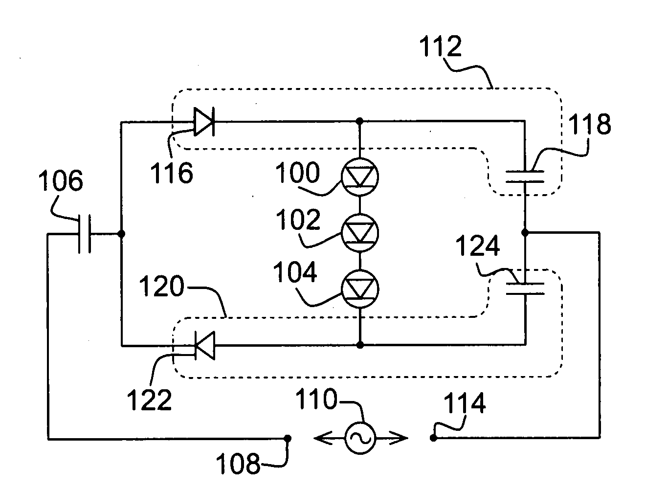
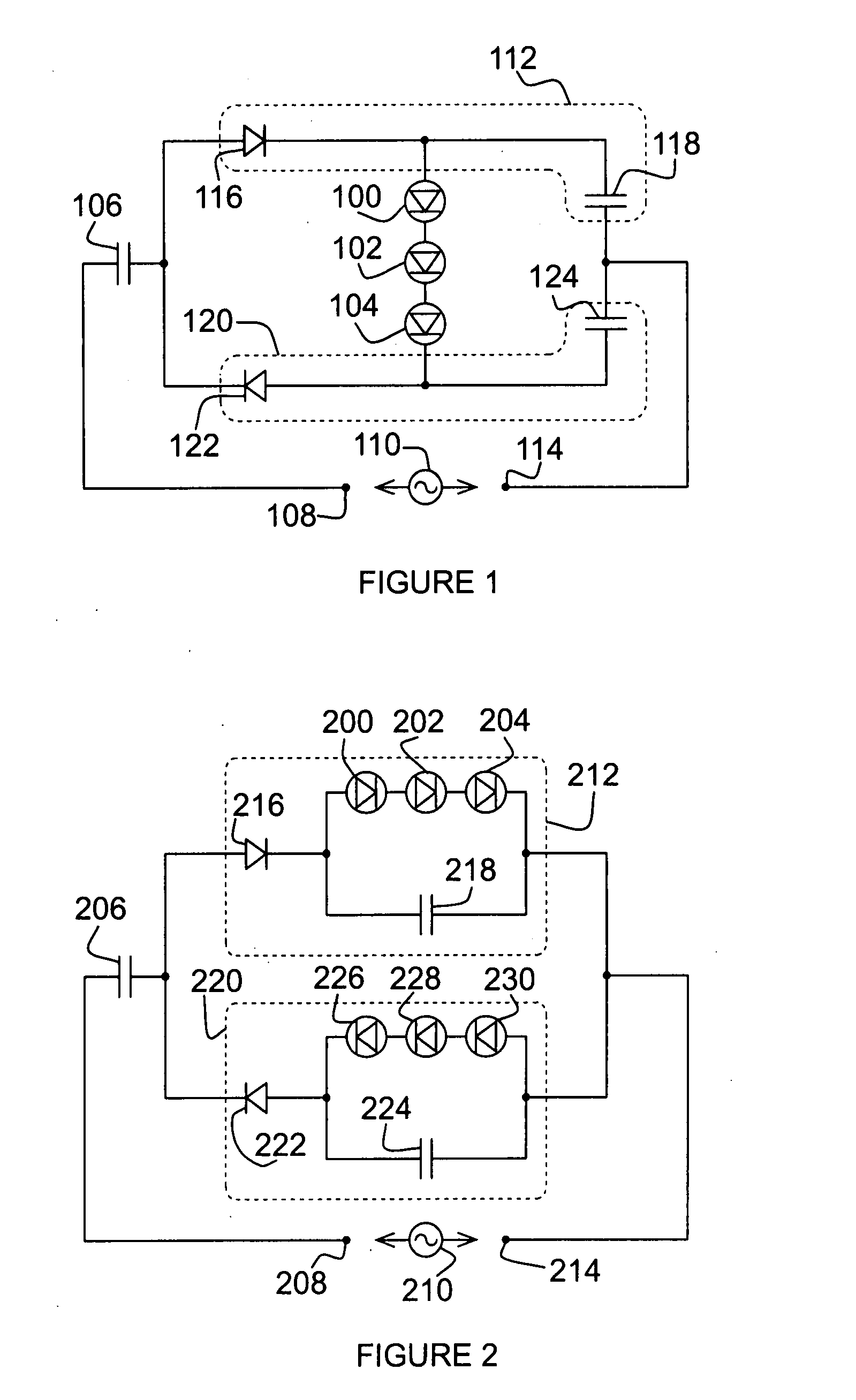
[0017]The present invention generally provides new techniques and driver circuits for powering light emitting diodes from an AC source of power. The drive circuits of the present invention significantly improve the potential for use of LEDs as a lighting source, by improving efficiency, eliminating flicker, and offering the flexibility of straightforward scalability.

[0018]In one embodiment, an alternating current drive circuit for supplying power to a light emitting diode includes a current limiting capacitor for connection to the first terminal of a source of alternating current, a first circuit portion connected between the current limiting capacitor and the second terminal of the source of alternating current, the first circuit portion including a first rectifying diode connected in series with a first power capacitor, and a second circuit portion connected, in parallel with the first circuit portion, between the current limiting capacitor and the second terminal of the source of...


PUM


Abstract

In an AC drive circuit for LEDs, a current limiting capacitor connects to an AC source, a first circuit portion, including a first rectifying diode and a first power capacitor, connects between the current limiting capacitor and the source and a second circuit portion, including a second rectifying diode in series with a second power capacitor, is in parallel with the first circuit portion. A first LED is in the first circuit portion in parallel with the first power capacitor, while a second LED in the second circuit portion is in parallel with the second power capacitor. During positive half cycles, the first rectifying diode charges the first power capacitor and drives the first LED. During negative half cycles, the second rectifying diode charges the second power capacitor and drives the second LED.

Description

BACKGROUND OF THE INVENTION[0001]1. Field of the Invention[0002]This invention relates to light emitting diodes (LEDs) and more particularly to electronic circuitry for providing power to LEDs from alternating current sources.[0003]2. Description of Related Art[0004]The many potential advantages of LEDs as a light source, compared to incandescent bulbs, may soon make LEDs viable as replacements for most applications currently using incandescents. LEDs are being developed with increasing amounts of light output—some currently available can provide about the same amount of illumination as a conventional 60 watt light bulb. LEDs are also relatively efficient with recent LED prototypes being demonstrated with a white light efficiency of 131 lumens per watt, while consuming only 20 mA of power.[0005]Moreover, improvements have been made in the color of the light produced by LEDs, and LEDs also have great advantages over incandescent bulbs with respect to longevity, since some LEDs can la...

Claims


Application Information

Patent Timeline
Patent Type & Authority Applications(United States)
IPC IPC(8): H05B37/00H01L33/00
CPCH05B33/0803Y02B20/342H05B33/0809H05B45/00Y02B20/30
Inventor WU, YIFENG
Owner IDEAL IND LLC
Why Eureka
Try Eureka