Path-Sharing Transceiver Architecture for Antenna Arrays

a transceiver and path-sharing technology, applied in the field of wireless signal processing, can solve the problems of consuming an excess amount of power, requiring an impractically large amount of semiconductor space, and consuming a large amount of power

Active Publication Date: 2008-10-16
UNIV OF SOUTHERN CALIFORNIA
View PDF3 Cites 22 Cited by
  • Summary
  • Abstract
  • Description
  • Claims
  • Application Information

AI Technical Summary

Benefits of technology

[0017]The present disclosure is directed to signal processing techniques suitable for timed arrays and phased arrays. This architecture allows coherent beam-forming.

Problems solved by technology

In addition, the power consumption and cost of UWB is usually lower compared to its conventional narrowband counterparts due to UWB's comparatively simpler detection schemes.
One challenge in the realization of a such an array is the effective implementation of the variable TTD structure.
However, such an implementation would require an impractically large amount of semiconductor space, as well as consume an excess amount of power.
Unfortunately, the transmission line characteristic impedance also varies while modifying the wave velocity, leading to unwanted reflection characteristics at different delay setting.
A similar challenge persists for artisans to develop a more compact, power efficient transceiver circuit for processing narrowband signals.
In short, the large size and high cost of integrated variable TTD blocks and phase shifters become major issues in conventional narrowband and broadband array architectures.

Method used


Image

  • Path-Sharing Transceiver Architecture for Antenna Arrays
  • Path-Sharing Transceiver Architecture for Antenna Arrays
  • Path-Sharing Transceiver Architecture for Antenna Arrays

Examples


Embodiment Construction

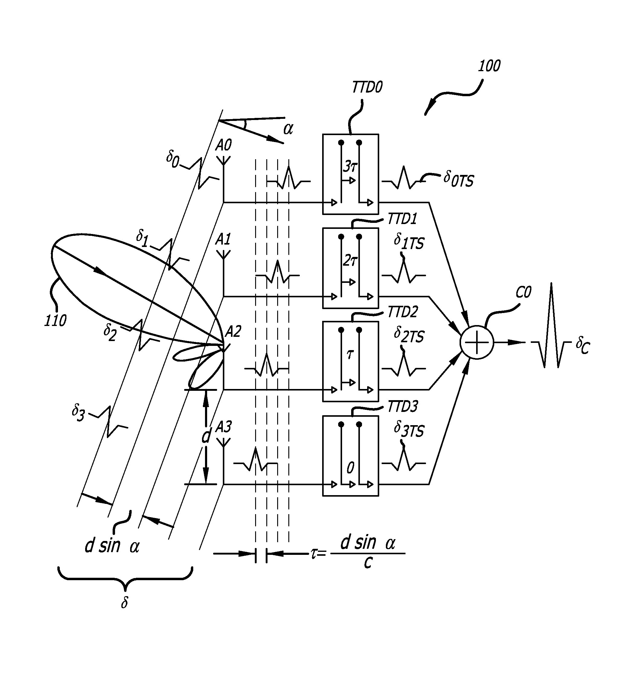
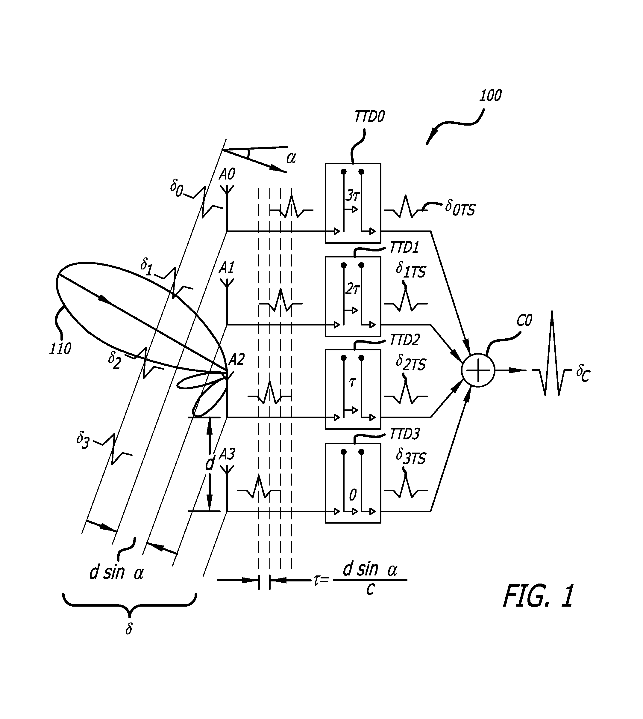
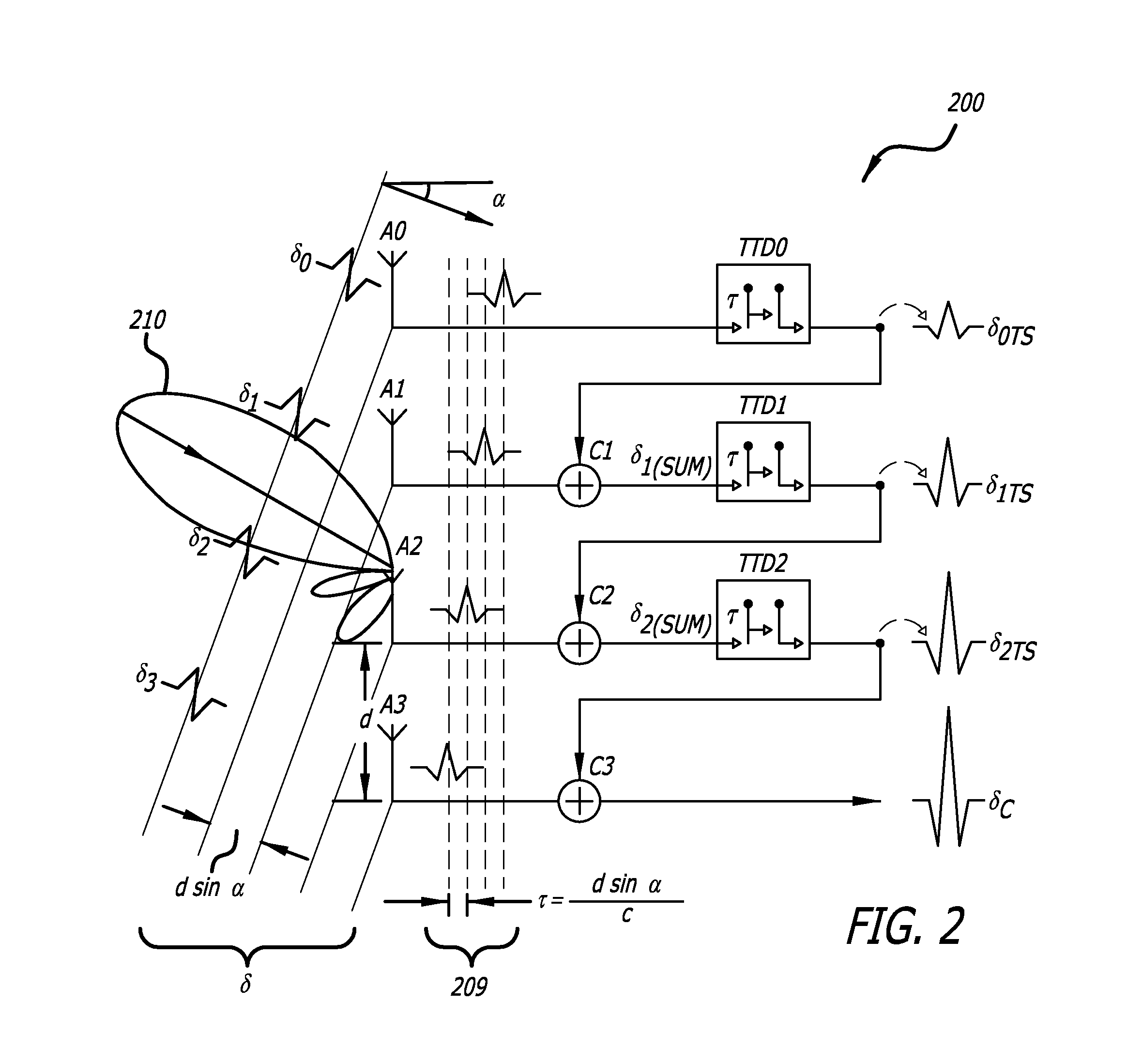
[0041]In UWB antenna arrays, the incident pulse reaches different antenna elements at different times as a function of the incident angle. The time delay difference between the signal on two adjacent antenna elements, τ, is a function of antenna spacing d and the incident angle α in accordance with the following relationship:

τ=dsin(α)c(1.1)

[0042]where c is the velocity of light. In a UWB imaging system, the time difference as quantified by equation (1.1) may be compensated by using a variable true time delay element in each channel to time shift earlier arriving signals and thereby align the signals for coherent addition.

[0043]For purposes of this disclosure:

[0044]One channel is adjacent to another when then antennas to which the channels are coupled are spatially adjacent. Thus, in FIG. 1, A1 is adjacent to A0, A2 is adjacent to A1, and A3 is adjacent to A3.

[0045]The phrase “coupled to” is not intended to convey that a direct coupling is required.

[0046]The phrase “shifted signal” m...


PUM


Abstract

A path sharing transceiver array architecture is disclosed. A plurality of channels are linked to antennas of an array for transmitting and receiving wireless signals that are offset in one of phase or time relative to one another. Each channel is associated with a delay element. In the receiving case, an offset signal is received at a first channel, processed, and shifted by a first delay element. The resulting signal is combined with the processed signal of a second, adjacent channel where a phase or time delayed signal is received. The combined signal is then shifted by a second delay element to produce a net signal. The first delay element is used to generate a shifted signal for both the first and second channel. The architecture can be extended to another number of channels.

Description

CROSS-REFERENCE TO RELATED APPLICATION[0001]This application claims priority to U.S. Provisional Patent Application Ser. No. 60 / 900,420, entitled “Novel Path-Sharing True Time Delay Transceiver Architecture For Ultra Wideband Antenna Arrays,” filed Feb. 9, 2007, attorney docket no. 28080-260, the contents of which are incorporated herein by reference in their entirety.STATEMENT REGARDING FEDERALLY SPONSORED RESEARCH[0002]This invention may have been made with government support under Boeing Phantom Works Grant No. KR-7716. The government may have certain rights in the invention.BACKGROUND[0003]1. Field of the Invention[0004]The present invention relates generally to wireless signal processing, and more specifically to circuit techniques for processing signals over antenna arrays.[0005]2. Description of Related Art[0006]The recent proliferation of ultra-wideband (UWB) communication and imaging applications has been widespread in both military and commercial arenas. The utilization of...

Claims


Application Information

Patent Timeline
Patent Type & Authority Applications(United States)
IPC IPC(8): H01Q3/00
CPCH01Q3/2682
Inventor CHU, TA-SHUNHASHEMI, HOSSEIN
Owner UNIV OF SOUTHERN CALIFORNIA
Why Eureka
Try Eureka