Image forming apparatus capable of efficient toner concentration control

a technology of toner concentration control and image forming apparatus, which is applied in the direction of electrographic process apparatus, instruments, optics, etc., can solve the problems of sensor not being able to accurately detect the amount of toner adhesive, the output value of the receiving device is declining, and the light reflection decreases

Inactive Publication Date: 2008-10-16
RICOH KK
View PDF20 Cites 26 Cited by
  • Summary
  • Abstract
  • Description
  • Claims
  • Application Information

AI Technical Summary

Benefits of technology

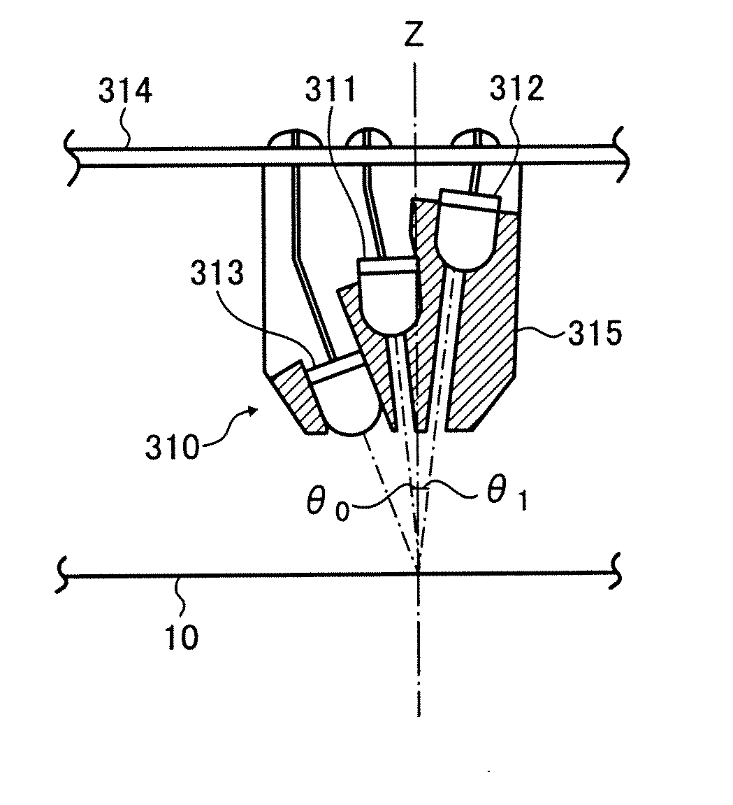
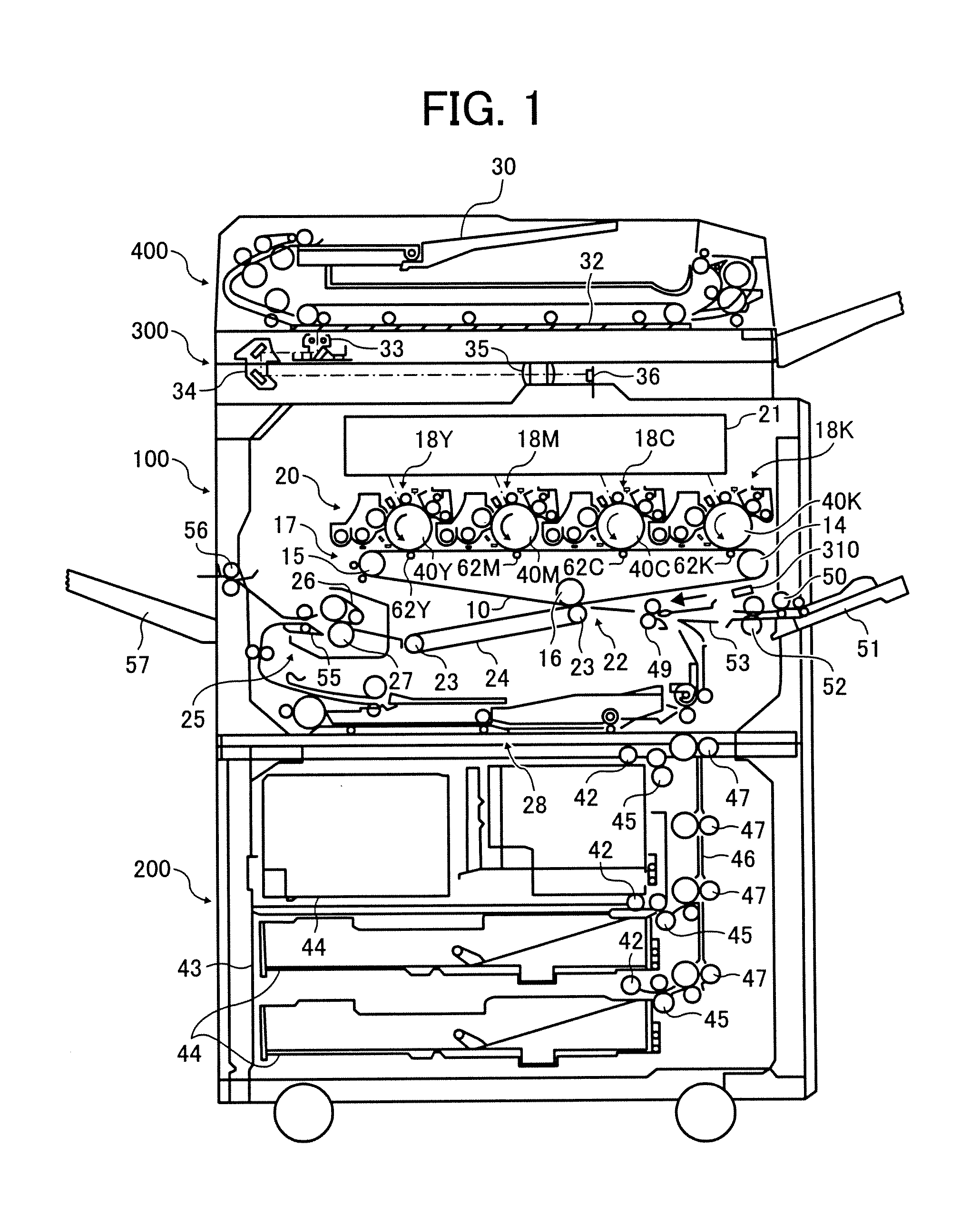
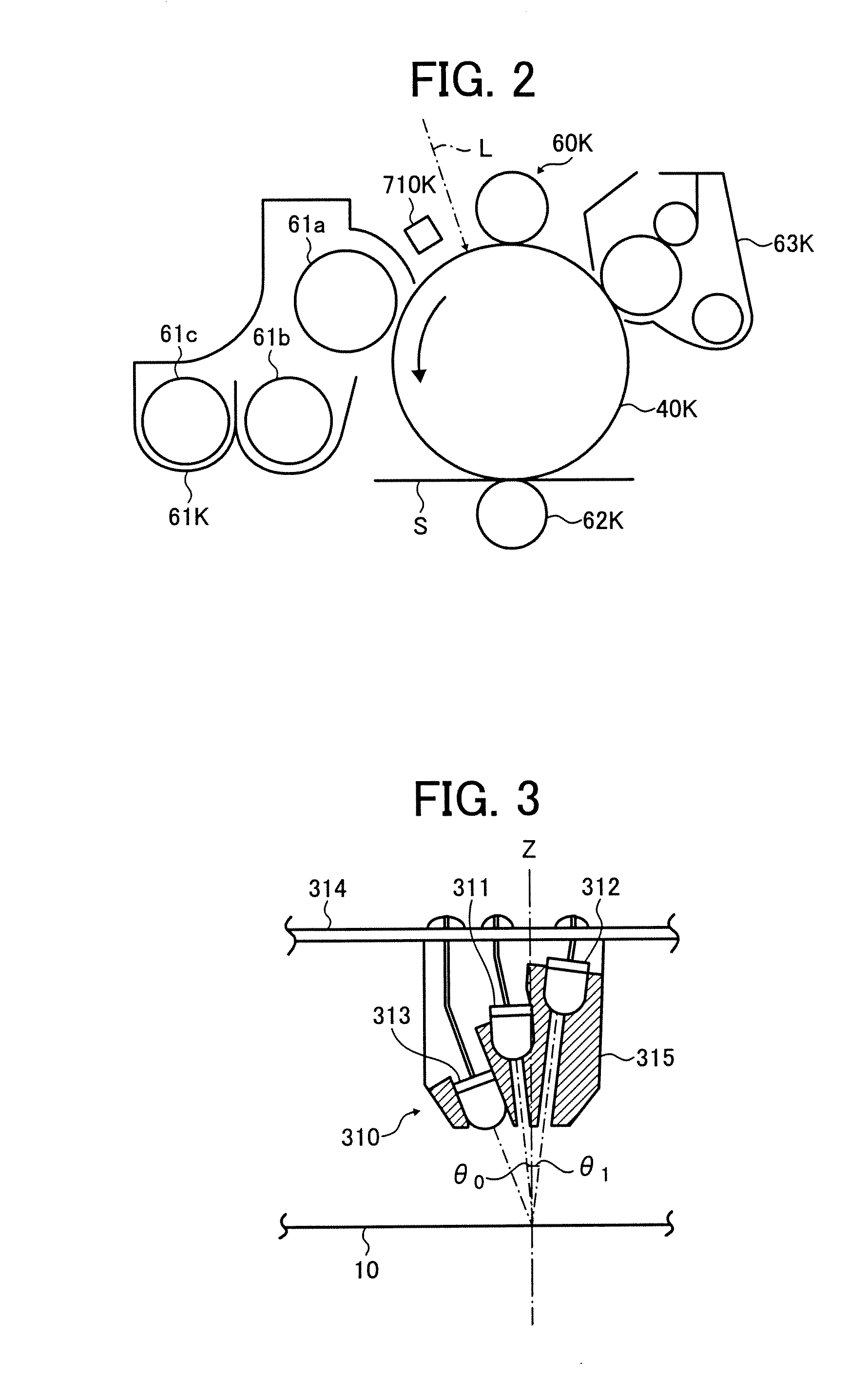
[0030]This patent specification describes a novel image forming apparatus including an image forming unit configured to form a plurality of toner images on an image carrier, an optical detector configured to detect reflection light from the toner image and dedicated to detect infrared rays and near-infrared rays, and a controller configured to perform a predetermined control using a detection results of the optical detector. A gradation pattern that is comprised of a plurality of toner patches formed in the image forming unit with an image forming condition to have different adhesive amounts, and is formed of at least two colors, and detection values detected by the optical detector are used for the predetermined control.

Problems solved by technology

On the other hand, when toner adhesive amount increases, the reflection light decreases because the surface to be detected becomes rougher due to accumulation of toner particles and the output value of the receiving device declines.
However, the regular-reflection type light sensor may not detect the toner adhesive amount of the toner patch accurately at a high concentration portion.
Output values of the emitting and receiving devices may change due to temperature dependence and aging of the emitting and receiving devices.
Further, the output value of the receiving device is changed due to degradation of the image carrier.
Therefore, it is not possible to perform toner concentration detection (toner adhesive amount detection) accurately when the toner adhesive amount is obtained solely from the detection value of the receiving device without adjustment (correction).
However, the cost of the system increases because more light sensors are necessary for each color.
Consequently, calculation accuracy does not improve even with a plurality of data points at equal positions.
However, the calculation accuracy does not improve if a plurality of data points are at an equal position.

Method used


Image

  • Image forming apparatus capable of efficient toner concentration control
  • Image forming apparatus capable of efficient toner concentration control
  • Image forming apparatus capable of efficient toner concentration control

Examples


experiment-1

[0196][Experiment-1]

[0197]The experiment-1 is an example experiment to form gradation pattern of each toner patch by uniformly distributing the LD on-duty of the exposure device 21 under the image potential of charge / development bias.

[0198]FIG. 14 is a graph representing potentials at exposure portion of each toner patch in the experiment. FIG. 15 is a graph representing a relation of the LD on-duty, and the ratio of the regular-reflection light output (ΔVsp_reg) and the diffuse-reflection light output (ΔVsp_dif) to calculate sensitivity correction coefficient α from the detection value of each toner patch detected by the light sensor. As shown in FIG. 15, data points around the minimum value of the ratio of the regular-reflection light output (ΔVsp_reg) and diffuse-reflection light output (ΔVsp_dif) are not overlapped but are distributed uniformly.

[0199]FIG. 16 is a graph plotted with the data points obtained from each toner patch in the effective range to calculate the sensitivity...

experiment-2

[0201][Experiment-2]

[0202]The experiment-2 is an example experiment to form gradation pattern of each toner patch by employing a fixed LD on-duty, and making a charge bias and a development bias variable. Specifically, the experiment-2 is the example experiment when the exposure device 21 is a multiple-value-writing system.

[0203]FIG. 17 is an illustration of outline graph representing surface potentials of the photoreceptor. As shown in FIG. 17, since exposure potentials are constant value, the charge-DC-bias and the development-DC-bias are changed to change the development potentials such that the toner adhesive amount of each toner patch is made different.

[0204]The toner adhesive amount of each toner patch formed in this procedure becomes similar adhesive amount to the adhesive amount of the experiment-1. As a result, the result can be shown in FIGS. 15 and 16 similarly. The data points that are necessary to calculate the sensitivity correction coefficients α and η are not overlap...


PUM


Abstract

An image forming apparatus includes an image forming unit configured to form a plurality of toner images on an image carrier, an optical detector configured to detect reflection light from the toner image, and dedicated to detect infrared rays and near-infrared rays, and a controller configured to perform a predetermined control using a detection results of the optical detector. Gradation pattern that is comprised of a plurality of toner patches formed in the image forming unit with an image forming condition to have different adhesive amounts, and is formed of at least two colors, and detection values detected by the optical detector are used for the predetermined control.

Description

CROSS-REFERENCE TO RELATED APPLICATION[0001]This patent specification is based on and claims priority from Japanese Patent Application No. 2006-274699, filed on Oct. 6, 2006 in the Japan Patent Office, the entire contents of which are incorporated by reference herein.BACKGROUND OF THE INVENTION[0002]1. Field of the Invention[0003]The present invention relates to an image forming apparatus, and more particularly, to an image forming apparatus capable of efficient toner-concentration control.[0004]2. Discussion of the Background[0005]An image forming apparatus that employs an electrophotographic method has been developed rapidly. Such an apparatus includes a printer, a copier, a facsimile machine, and a multi-function system, for example. Recently, there is increasing demand that such image forming apparatus has high reliability to provide high quality images.[0006]Such image forming apparatus commonly employs the following image concentration control method to maintain an excellent i...

Claims


Application Information

Patent Timeline
Patent Type & Authority Applications(United States)
IPC IPC(8): G03G15/00
CPCG03G2215/00059G03G2215/00063G03G15/0131G03G15/5058
Inventor ISHIBASHI, HITOSHIHASEGAWA, SHINFUJIMORI, KOHTATAKEUCHI, NOBUTAKATANAKA, KAYOKOHIRAYAMA, YUSHITOMITA, KENTAROHHIRAI, SHUJI
Owner RICOH KK
Why Eureka
Try Eureka