Cage nut fastening system

a cagenut and fastening technology, applied in the direction of fastening means, screws, threaded fasteners, etc., can solve the problems of inaccessible hydro-form tubes, conventional fastening joints, 1 and 2, do not provide high clamp load retaining forces, etc., and achieve the effect of increasing clamping and retaining forces

Inactive Publication Date: 2008-10-16
ILLINOIS TOOL WORKS INC
View PDF7 Cites 7 Cited by
  • Summary
  • Abstract
  • Description
  • Claims
  • Application Information

AI Technical Summary

Benefits of technology

[0007]Embodiments of the present invention provide a fastening assembly that provides increased cl

Problems solved by technology

Typical hydro-form tubes are inaccessible to internal place threaded fasteners due to the closed nature of the tubes.
Conventional fastening joints, such as are shown in FIGS. 1 and 2, do not, however, provide high clamp load retaining

Method used


Image

  • Cage nut fastening system
  • Cage nut fastening system
  • Cage nut fastening system

Examples


Embodiment Construction

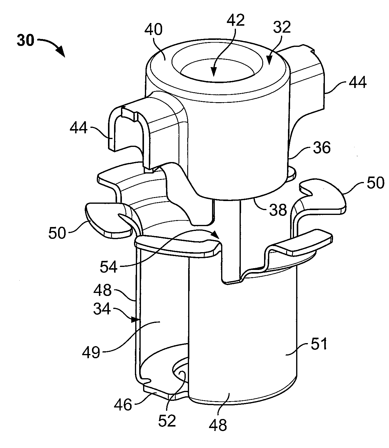
[0033]FIG. 3 illustrates an isometric exploded view of a cage-nut fastener assembly 30 according to an embodiment of the present invention. The fastener assembly 30 may be used with respect to hydro-form tube applications. In general, the fastener assembly is used to secure and fasten objects to sheet metal type components.

[0034]The fastener assembly 30 includes a nut 32 and a cage 34. Both the nut 32 and the cage 34 may be deep draw stampings. The nut 32 may be formed through a press-tap-press process. For example, the nut 32 may be extruded from flat stock. Rolled inline threads may then be formed on or within the nut 32.

[0035]The nut 32 includes a generally cylindrical main body or wall 36 that connects lower edges 38 to a rounded upper surface 40. A fastener through-hole 42 is formed through the rounded upper surface 40 and extends through at least a portion of the length of the main wall 36. The fastener through-hole 42 may be threaded or unthreaded, depending on the type of fa...


PUM


Abstract

A cage-nut assembly is configured to securely clamp to at least one panel. The assembly includes a cage including an annular base integrally connected to beams having flat tabs extending from ends thereof. A nut chamber is defined between the annular base and the beams. A nut is positioned within the nut chamber, wherein at least one of the flat tabs prevents the nut from ejecting from the cage. The panel is configured to be clamped between the flat tabs and a portion of the nut.

Description

RELATED APPLICATIONS[0001]This application relates to and claims priority benefits from U.S. Provisional Patent Application No. 60 / 923,045 entitled “Cage Nut Fastening Assembly,” filed Apr. 12, 2007, which is hereby incorporated by reference in its entirety.FIELD OF THE INVENTION[0002]Embodiments of the present invention generally relate to a fastening assembly, and more particularly to a two-piece threaded cage-nut fastening system.BACKGROUND OF THE INVENTION[0003]Various vehicle assemblies include tubes, such as hydro-form tubes, that are used for structural support and for connecting various components together. Typical hydro-form tubes are inaccessible to internal place threaded fasteners due to the closed nature of the tubes. Thus, in order to secure one tube to another component, such as a vehicle panel or another tube, the base material of the tube, which may include a single threaded form to accept a threaded fastener, is used.[0004]FIG. 1 illustrates an isometric view of a ...

Claims


Application Information

Patent Timeline
IPC IPC(8): F16B37/04
CPCF16B37/044
Inventor JOHNSON, LAWRENCE W.MARTINS, MANUEL J.MOLINA, HECTOR A.
Owner ILLINOIS TOOL WORKS INC
Why Eureka
Try Eureka