Presence of communication interlock method and apparatus for reducing or eliminating aircraft communications radio interference

a communication interlocking and aircraft technology, applied in the field of aircraft onboard radio communication, can solve the problems of affecting the operation of the communication interlocking device, so as to reduce the potential for interference, reduce the interference potential, and increase the physical distance

Inactive Publication Date: 2008-10-16
EMBRAER SA
View PDF6 Cites 12 Cited by
  • Summary
  • Abstract
  • Description
  • Claims
  • Application Information

AI Technical Summary

Benefits of technology

[0010]There have been past efforts to minimize such interference. Some past approaches have used traditional processes involving antenna separation. Increasing the physical distance between antennas mounted on the aircraft fuselage can reduce the potential for interference. Antennas mounted on the same side of the aircraft are generally provided at a minimum separation (e.g., 38 feet) to achieve necessary isolation. However, size limitations on business and regional aircraft can preclude installing the antennas with spacing adequate to provide 40 dB of isolation necessary to prevent cross talk.

Problems solved by technology

One problem encountered in the past relates to interference between other on-board co-band or other radios.
The autonomously-initiated ACARS VHF transmissions can cause interference to other active onboard receivers operating on the same (e.g., VHF) radio band.
For example, when ACARS begins transmitting a data burst, a voice communications radio in the process of receiving a tower or other voice communication may produce a chirp noise.
Such chirp noise “interference” can significantly disrupt the operation of the other active VHF transceivers in the vicinity and cause problems with intelligibility.
However, size limitations on business and regional aircraft can preclude installing the antennas with spacing adequate to provide 40 dB of isolation necessary to prevent cross talk.
However, Simulcom may not eliminate cross talk in all cases.
This could minimize any interference during critical communications with ATC but has its own set of issues.

Method used


Image

  • Presence of communication interlock method and apparatus for reducing or eliminating aircraft communications radio interference
  • Presence of communication interlock method and apparatus for reducing or eliminating aircraft communications radio interference
  • Presence of communication interlock method and apparatus for reducing or eliminating aircraft communications radio interference

Examples


Embodiment Construction

[0020]The following disclosure provides an exemplary illustrative non-limiting implementation for reducing or eliminating undesirable chirp noise that can be caused by the ACARS system and associated VHF on aircraft communications systems.

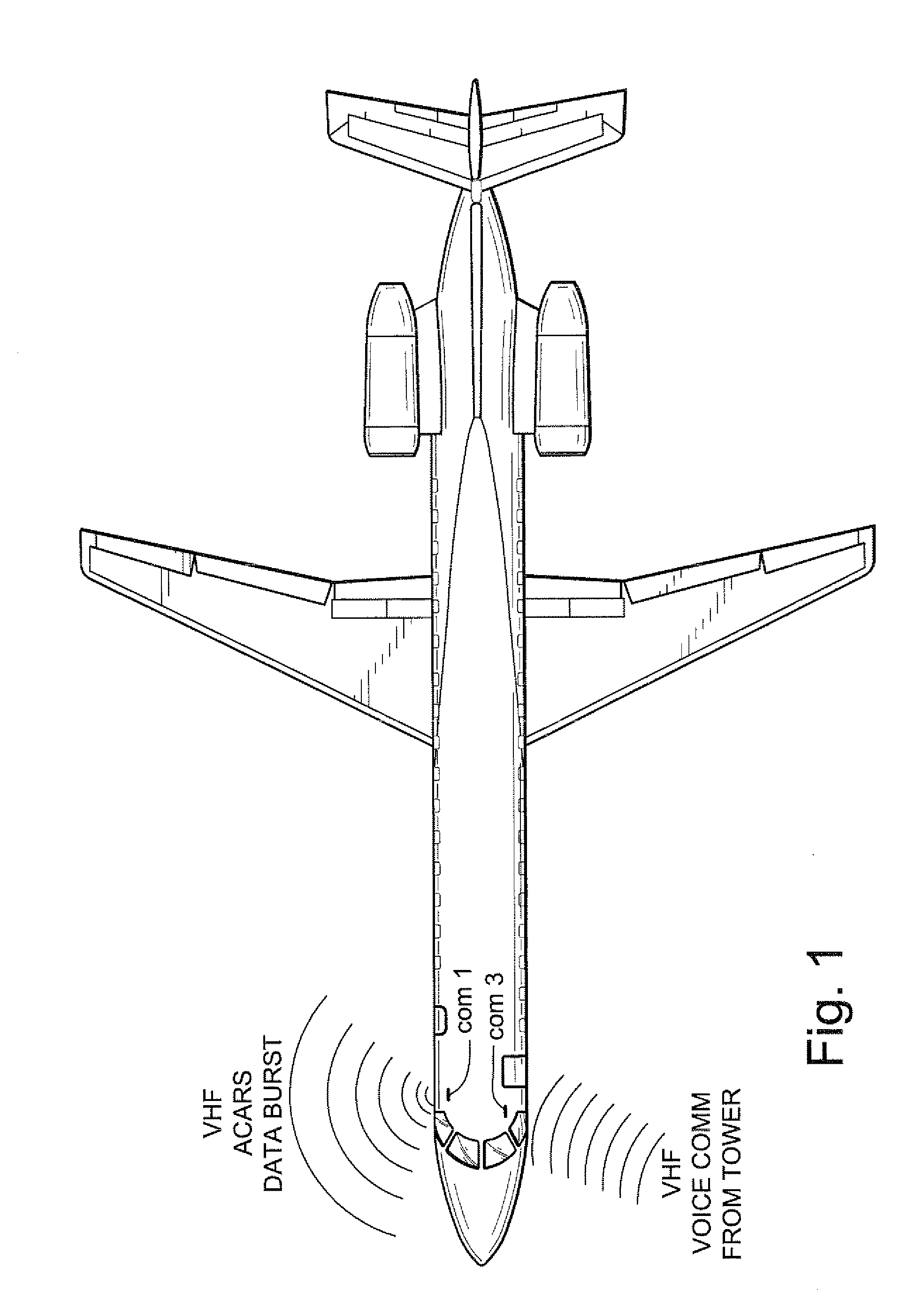
[0021]In one exemplary illustrative non-limiting implementation, Comm 1 and Comm 3 antennas are installed on the same side of the aircraft (e.g., top). See FIG. 1. Other installations may for example rely on a minimum antenna separation (e.g., 38 feet) for antennas that are installed on the same side of the aircraft. While other techniques can be used to reduce the splashovers, it is not unusual to continue to get splashover when VHF 1 or VHF 2 operate at close to the frequency of ACARS.

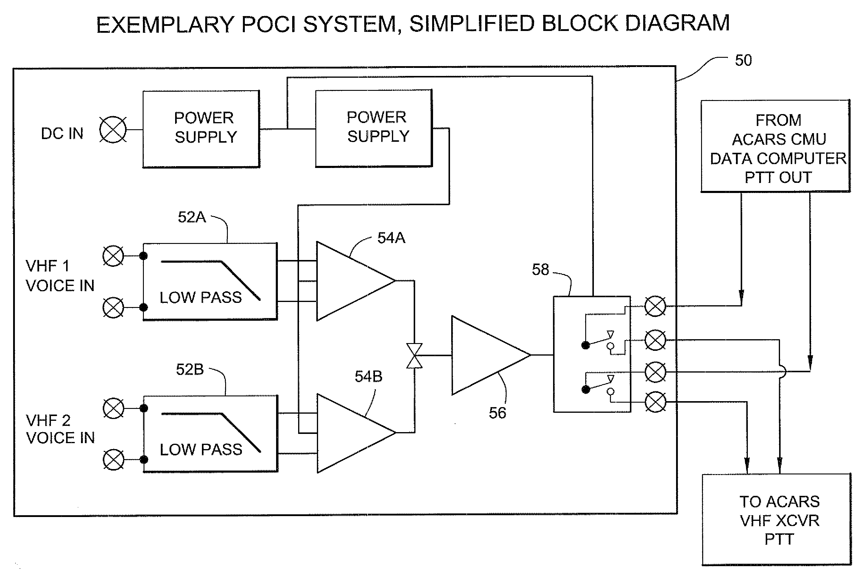
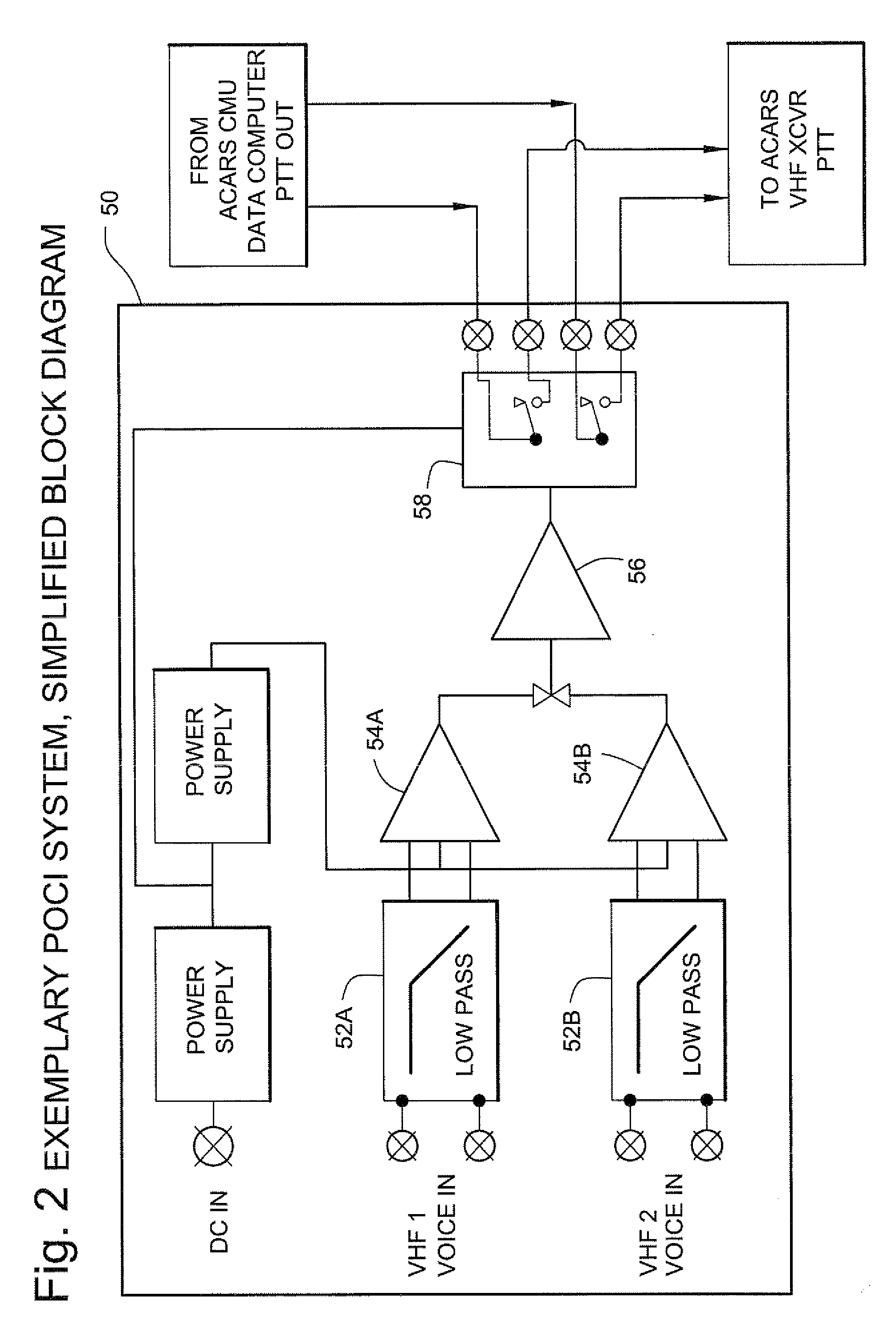
[0022]In one exemplary illustrative non-limiting implementation, a “POCI” (Presence Of Communication Interlock) 50 is provided to prevent the ACARS transmitter from transmitting during times when other radios (e.g., VHF1, VHF2) are actively receiving voice communica...


PUM


Abstract

In one exemplary illustrative non-limiting aircraft radio communications system, a “POCI” (“Presence Of Communication Interlock”) is comprised of a double balanced low pass LC filter covering the voice range. The voice signals coming from the two VHF's are filtered and processed by an amplifier at an adequate level to be peak detected. The resulting signal is applied to an amplifier with a defined hysteresis and time constant and finally drives the relay interlock circuit that inhibits an ACARS VHF radio from transmitting whenever other on-board comm. VHF transceivers are receiving voice signals. Visual indicators provide information on system operation and system power failure.

Description

CROSS-REFERENCE TO RELATED APPLICATIONS[0001]Not applicable.FIELD[0002]The technology herein relates to aircraft onboard radio communications, and more particularly to method and apparatus for reducing or eliminating VHF (Very High Frequency) or other radio interference on board an aircraft. Still more particularly, the technology herein relates to an arrangement for interlocking or inhibiting ACARS data transmission during active voice reception.BACKGROUND AND SUMMARY[0003]Air-to-ground and air-to-air radio communications are important to safe aircraft flight. Modern aircraft are equipped with a multitude of radio communications systems, many of them operating in generally the same Very High Frequency (VHF) radio band (30 MHz to 300 MHz). These various radio systems allow the aircraft to remain in essentially constant communication with the ground. Flight crews use so-called “comm” voice radios to talk with air traffic controllers to get clearance to take off, land, change altitude...

Claims


Application Information

Patent Timeline
Patent Type & Authority Applications(United States)
IPC IPC(8): H04B1/38
CPCH04B7/18506
Inventor WHITAKER FILHO, NELSON
Owner EMBRAER SA
Why Eureka
Try Eureka