
Method for Monitoring the Depth of Anesthesia

a technology of anesthesia and depth, applied in the field of monitoring the depth of anesthesia, can solve the problems of affecting the patient, reducing so as to achieve the effect of improving the accuracy of anesthesia

Inactive Publication Date: 2008-10-16
YUAN ZE UNIV
View PDF5 Cites 21 Cited by
  • Summary
  • Abstract
  • Description
  • Claims
  • Application Information

AI Technical Summary

Benefits of technology

[0021]step 3: multiplying the approximate entropy value obtained in step 2 by 1000/17, and by using this corrected value as the predi

Problems solved by technology

In the course of operation, either over or under dosage of anesthetics will cause adverse effects on the patient.
Furthermore, since patients under such situations cannot breathe by themselves and are inactive, a false perceived depth of anesthesia may be consequently produced.
Thereby, the anesthesiologist might lose an important objective estimation criterion, and hence could not readily monitor or detect the true anesthesia state of a patient.
However, when the electric resistivity on the skin of a patient is high, the predictability from both of SEF95 and MEF is poor.
Suchuckers[13] used approximate entropy instead of standard deviation analysis to distinguish the difference of heart beat between ventricular fibrillation and non-ventricular fibrillation, because the traditional standard deviation analysis failed to observe the regularity of a signal and also could not differentiate effectively a disease.
Nevertheless, since BIS and AEP equipments are expensive, they are not widely available in every operation room and in every hospital.
Moreover, since its theory has not been fully disclosed, physicians cannot effectively master material information to monitor and detect depth of anesthesia, which in turn may result in anesthesia of a patient that is of too deep or too shallow.
Such undesirable situation increases the risk in the operation.
Accordingly, the methods for predicting depth of anesthesia mentioned above have many disadvantages, and they are not perfect designs and need to be improved urgently.

Method used


Image

  • Method for Monitoring the Depth of Anesthesia
  • Method for Monitoring the Depth of Anesthesia
  • Method for Monitoring the Depth of Anesthesia

Examples


example 1

The Collection of Clinical Data

1. The Investigated Subject

[0033]The investigated subjects of this example were patients to be subjected to an operation of nasosinusitis in National Taiwan University Hospital. Twenty-five patients were enrolled. Thirteen of them are male, and the other twelve are female. They are in an average age of 42+13 years, and the average operation time is 110±45 minutes. The patient being tested was made first into anesthesia by intravenous injecting with thiopental. Then, the anesthesia manner was changed into general gas anesthesia (general anesthesia using inhalant anesthetics), which the main inhalant anesthetics were isoflurane, sevoflurane, and desflurane.

2. Measuring Instruments and Data Collection

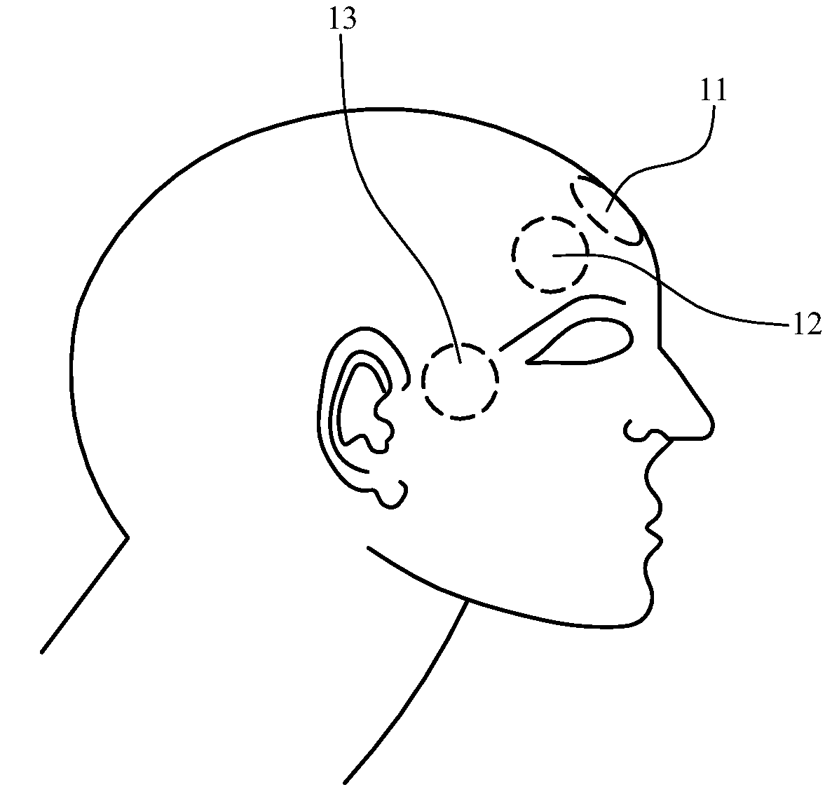
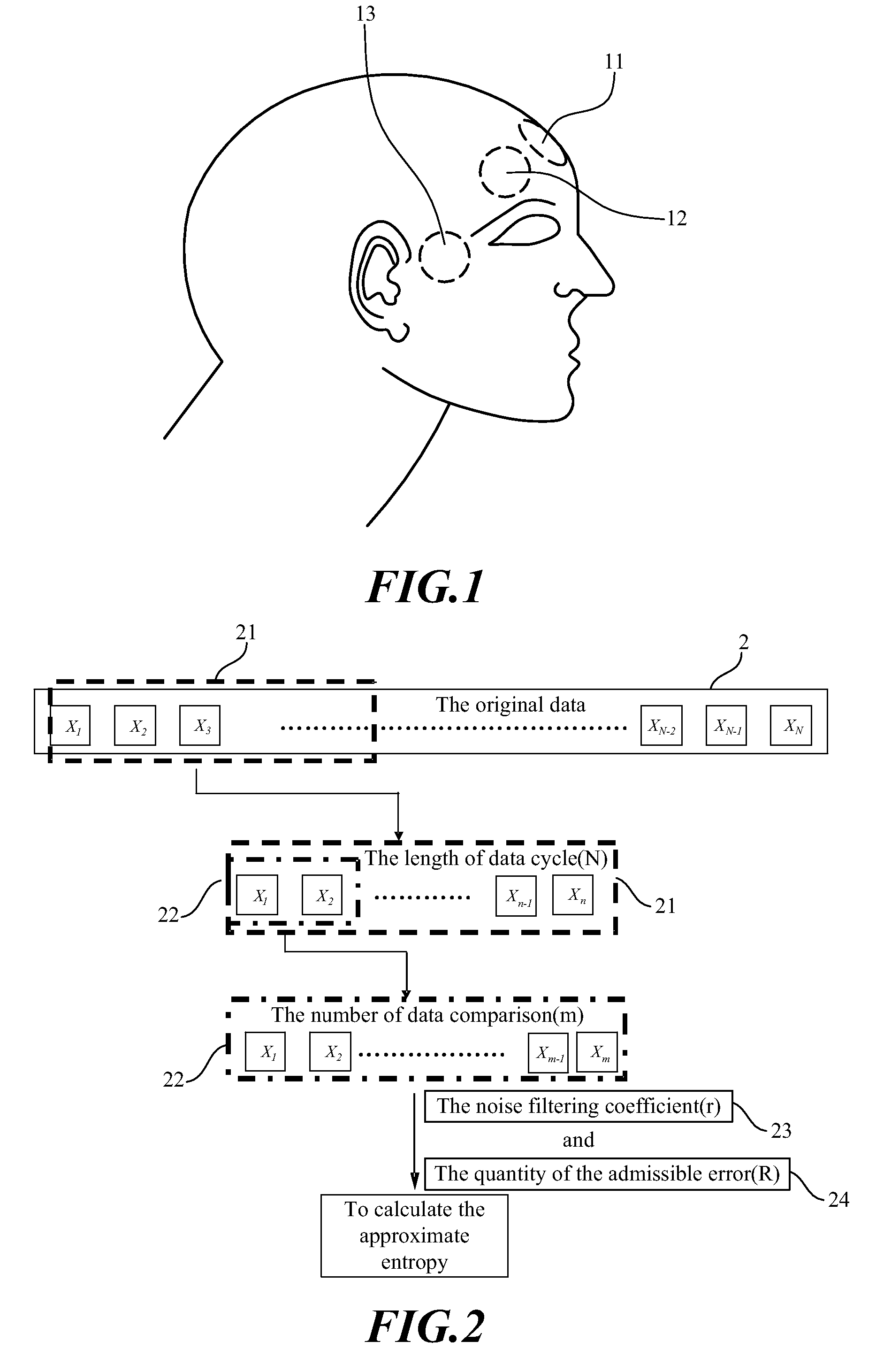
[0034]In this example, the brain wave signal, BIS Index, SEF95, and MEF of the anesthetized subject was collected with a BIS Monitor (Aspect A-1050). As shown in FIG. 1, the brain wave measuring patch was attached on the center (CTR) 11, ground (GND) 12, and ...

example 2

Analysis of Brain Wave Signals With Approximate Entropy

[0045]In this example, the brain wave signal of the subject was analyzed with approximate entropy, and the result of which was used to predict further the depth of anesthesia of the subject. Low approximate entropy value indicated the anesthesia state of the subject, where the brain wave signal had a regularity and predictability. On the contrary, high approximate entropy value represented the irregularity and non-predictability of the brain wave signal from the subject, which in turn indicated that the subject was readily to regain consciousness. The approximate entropy was calculated as follows:

Approximat Entropy=Φm(r)−Φm+1(r)   (1)

wherein

Φm(r) is defined as in the following formula (2):

Φm(r)=(N-m+1)-1·∑i=1N-m+1lnCim(r)(2)

Cim(r) is defined as in the following formula (3):

Cim(r)=(number of x(j) such that d[x(i),x(j)]≦r) / (N−m+1)   (3)

x(i) and x(j) are defined as in the following formula (4):

x(i)=[u(i), . . . , u(i=m−1)]

x(j)=[u(j...

example 3

Results

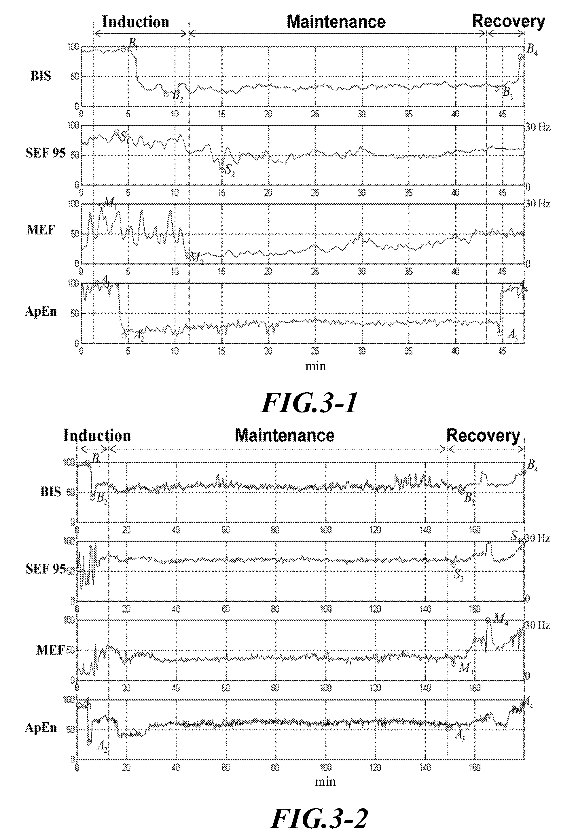
[0070]FIG. 3-1 to 3-25 shows analytical value of BIS Index, SEF95, MEF, and approximate entropy obtained during the anesthesia period of the subject tested. Next, the anesthesia course was divided into three phases, i.e., induction, maintenance and recovery, and thereafter, the depth of anesthesia of the subject in each phase was analyzed using BIS Index, SEF95, MEF, and approximate entropy. Results were shown in Table 1, 2 and 3.

TABLE 1The depth of anesthesia of the subject in induction phase of anesthesiausing BIS Index, SEF95, MEF and approximate entropyBIS IndexSEF95MEFApEnPatientmeanSDmeanSDmeanSDmeanSD 173.927.674.56.156.21861.835.9 276.718.959.620.128.817.369.216.7 376.718.959.620.128.817.369.216.7 479.226.172.322.925.722.373.628.9 579.221.662.120.723.112.984.119.5 679.221.662.120.739.526.471.117.1 780.617.670.316.329.424.680.616.3 885.815.560.427.123.415.373.713.6 984.318.664.519.525.517.679.118.31067.719.856.31820.318.276.814.91182.921.754.744.224.321.475.421.81289.2...


PUM


Abstract

A method for monitoring the depth of anesthesia is provided for detecting the conscious state of one being anesthetized in order to facilitate an anesthesiologist to predict exactly the dosage of an anesthetic required. At first, an original electroencephalogram (EEG) is taken from one being tested. Then, the original electroencephalogram is analyzed by approximate entropy to obtain its approximate entropy value. Next, the approximate entropy value is multiplied by 1000 / 17, and the corrected value is assumed as the predicted value of depth of anesthesia. The predicted value of depth of anesthesia represents degree of the conscious state or the depth of anesthesia for the one being tested. The higher the predicted depth of anesthesia value, the more conscious the one being tested is, i.e., in a shallower depth of anesthesia. On the other hand, the lower the predicted depth of anesthesia value, the less conscious the one being tested is, i.e., in a deeper depth of anesthesia.

Description

BACKGROUND OF THE INVENTION[0001]1. Field of the Invention[0002]The invention relates to a method for monitoring the depth of anesthesia, and in particular, a method for monitoring the depth of anesthesia based on the theory of approximate entropy.[0003]2. Description of the Prior Art[0004]Anesthesia is an indispensable part of surgery. In the course of operation, either over or under dosage of anesthetics will cause adverse effects on the patient. As a traditional anesthesia method, an anesthesiologist monitors depth of anesthesia in a patient under anesthesia based on observations on the underlying change of physiological symptoms such as breathing rates, the blood pressure, the heart beat, eye signs and the like as well as the patient's physical response to stimulation caused by the operation procedure. However, in the process of anesthesia, a muscle relaxant might be used as an auxiliary drug to have better muscle relaxant effect on the patient during the surgical operation. A m...

Claims


Application Information

Patent Timeline
IPC IPC(8): A61B5/04
CPCA61B5/0476A61B5/4821A61B5/369A61B5/372
Inventor SHIEH, JIANN-SHINGCHEN, BO-CUNFAN, SHOU-ZEN
Owner YUAN ZE UNIV
Learn More