
Allograft spinal facet fusion system

a spine and facet fusion technology, applied in the field of surgical implant systems, can solve the problems of reducing function, limiting rotation, and increasing stress on adjacent non-fused motion segments by spine fusion

Active Publication Date: 2008-10-16
HORTON KENNETH L
View PDF45 Cites 140 Cited by
  • Summary
  • Abstract
  • Description
  • Claims
  • Application Information

AI Technical Summary

Problems solved by technology

While spine fusion generally helps to eliminate certain types of pain, it has also been shown to decrease function by limiting the range of motion for patients in flexion, extension, rotation and lateral landing.
Furthermore, it is believed that spine fusion creates increased stresses on adjacent non-fused motion segments.
The facet's articular surfaces contact in extension, limiting rotation and increasing compressive load.
However, one of the root causes of back pain, particularly the persistent and disabling kind, is facet joints.
The articular cartilaginous surfaces can degenerate due to mechanical or biological factors and cause pain as with other joint osteoarthritis.
Furthermore, problems with the facet joints can also complicate treatments associated with other portions of the spine.
There is currently a lack of suitable intervention procedures for facet joint disorders.
There are several types of metal facet screws for fusion of facet joints but the metal screws compromise a large surface area of the facet, predisposing the facet to fracture.
Consequently, the use of metal screws for fusion of facet joints is risky.
Tapered allograft dowels are known but there is nothing on those devices to prevent their migration from the place of insertion.
Other types of allograft dowels have threads, but the threads tend to break.
Interference allograft screws are known but are not suitable for use with facets.
A molly bolt-type fusion mechanism with a gun inserter is known but does not provide the surgeon sufficient control when working with the spine.

Method used


Image

  • Allograft spinal facet fusion system
  • Allograft spinal facet fusion system
  • Allograft spinal facet fusion system

Examples


Embodiment Construction

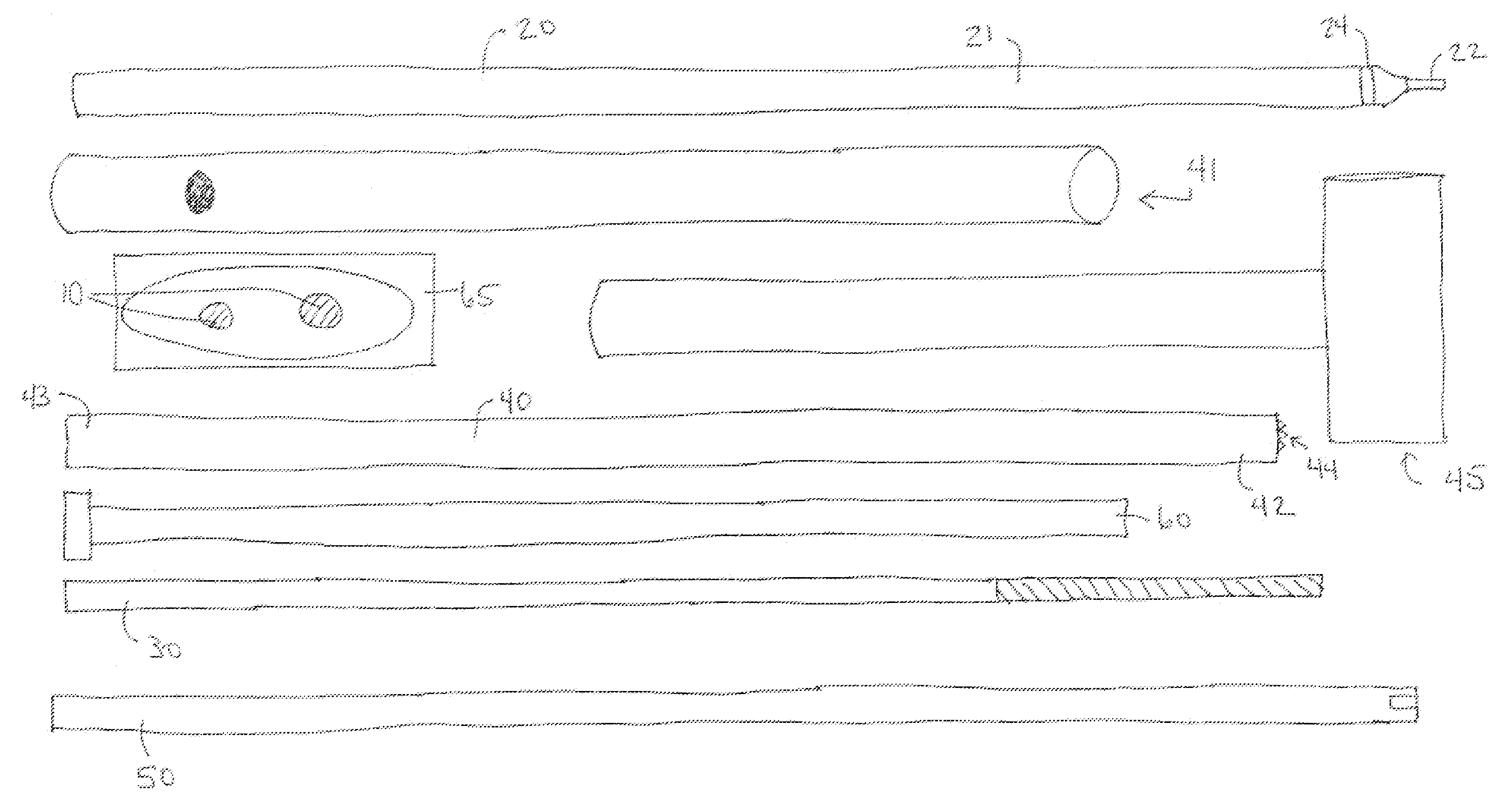
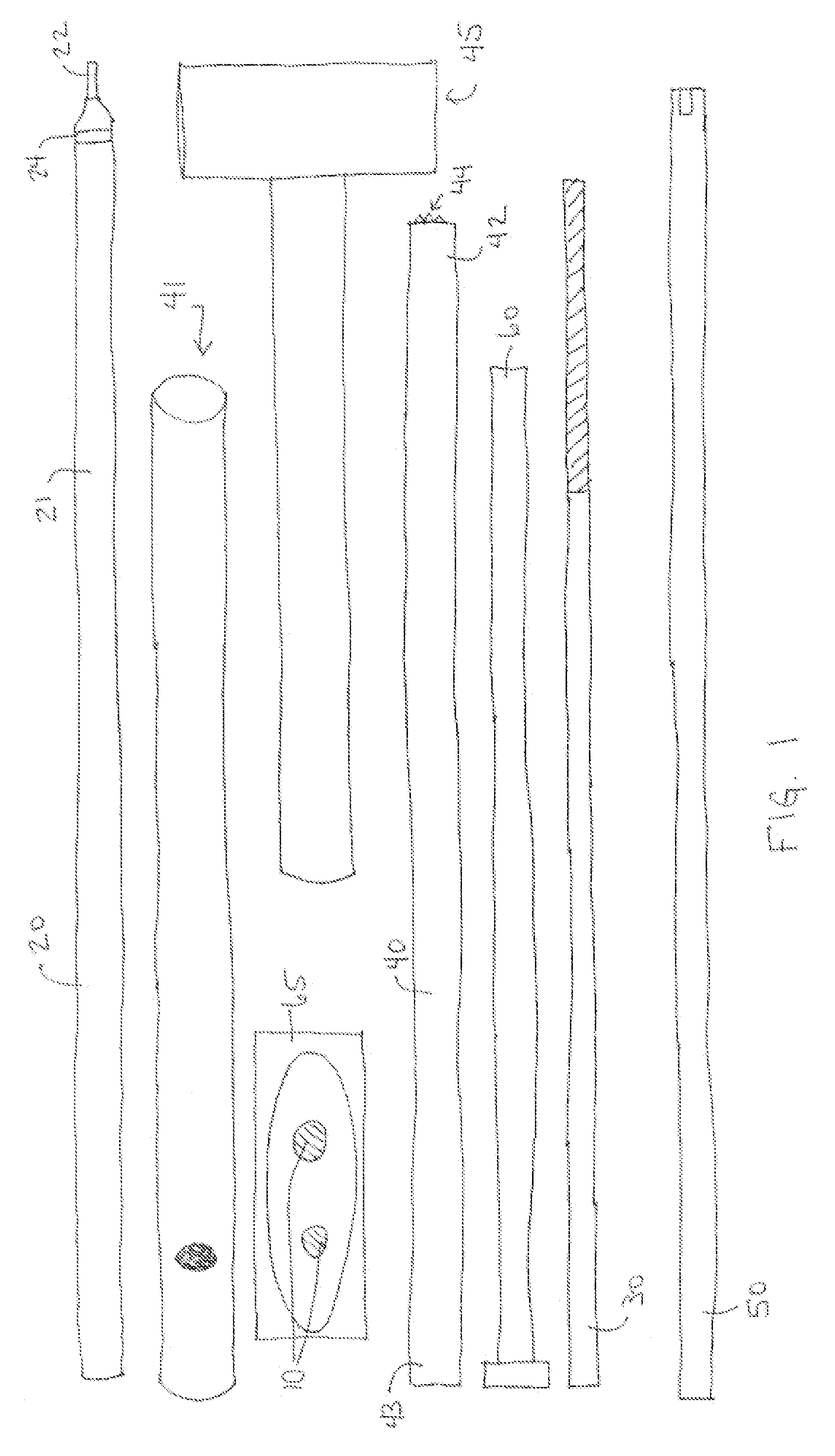
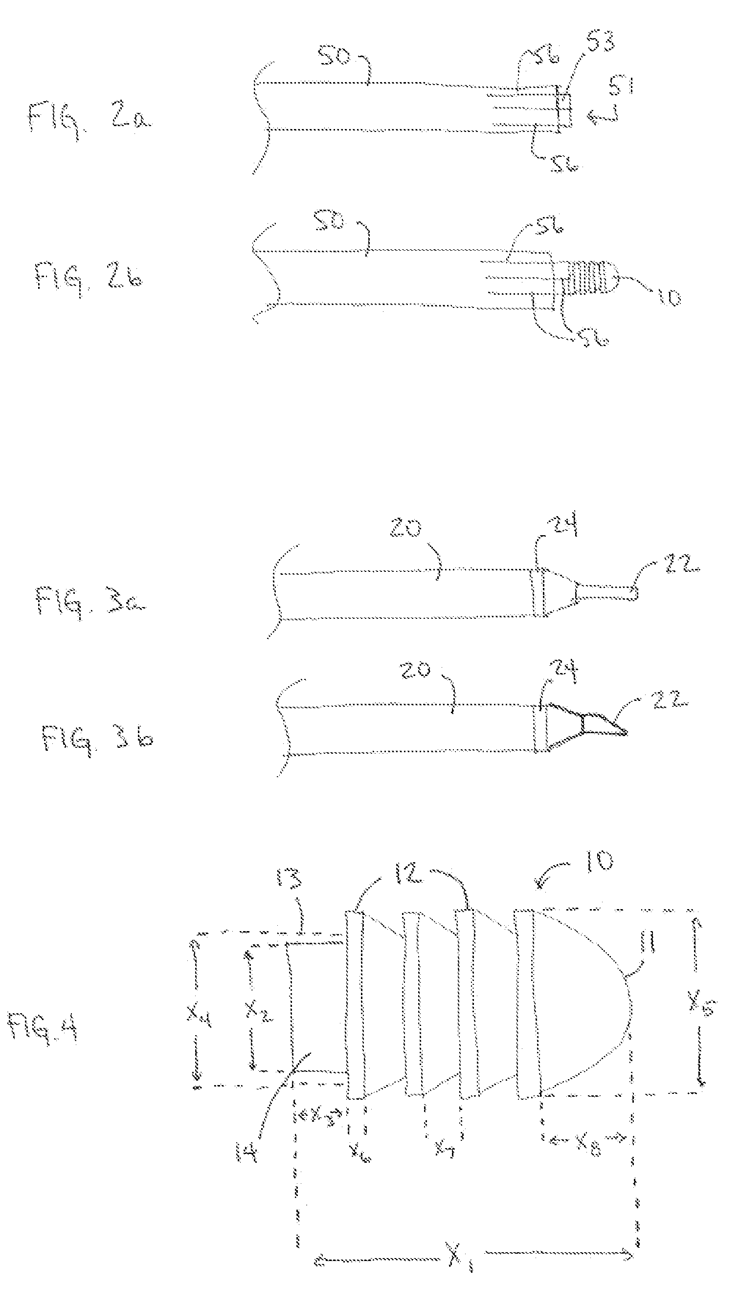
[0015]The system of the present invention for spinal facet joint fusion comprises a bullet-shaped allograft implant 10, best shown in FIG. 4, preferably harvested from human cortical bone. The allograft implant 10 is unidirectional with anti-migration properties that prevent back-out from the point of insertion into the facet joint. The distal end 11 of the implant 10 is convex in shape for easier insertion into the facet joint. Fins 12 on the shaft 13 of the implant 10 provide an increased surface area. The increased surface area provides more area to distribute forces for healing in addition to preventing back-out. Fins 12 allow for increased perfusion of blood around the graft. During the surgical procedure for inserting the implant 10 more blood surrounds the implant 10, which is good for stabilization. The proximal end 14 of the implant 10 is formed with a slightly smaller diameter such that when the implant inserter 50 engages the implant 10, the surgeon will be able to see th...


PUM


Abstract

A method for fusing a spinal facet joint and a surgical kit for use therein. The kit preferably comprises an allograft implant, a facet finder, a drill, a drill guide, and an implant inserter. The method preferably comprises the steps of locating the facet joint with a facet finer, sliding a drill guide over the facet finder until the drill guide engages the facet joint, removing the facet finder from within the drill guide, inserting a drill through the drill guide and drilling a socket within the facet joint to a predetermined depth, removing the drill from within the drill guide, securing an allograft implant within an implant inserter, inserting the implant inserter through the drill guide until the implant engages the socket, tapping the implant inserter to push the implant completely within the socket, removing the implant inserter from within the drill guide, and removing the drill guide.

Description

REFERENCE TO RELATED APPLICATION[0001]The present application claims priority to U.S. Provisional Application No. 60 / 911,683, filed on Apr. 13, 2007, the disclosure of which is incorporated herein by reference.FIELD OF THE INVENTION[0002]The present invention relates to surgical implant systems, and more particularly, to allograft implant methods used to fuse spinal vertebrae sod surgical kits therefore.BACKGROUND OF THE INVENTION[0003]A common surgical invention is spine fusion, in which two or more adjacent vertebral bodies are fused together in order to alleviate pain associated with the disc(s) located between those vertebral bodies. While spine fusion generally helps to eliminate certain types of pain, it has also been shown to decrease function by limiting the range of motion for patients in flexion, extension, rotation and lateral landing. Furthermore, it is believed that spine fusion creates increased stresses on adjacent non-fused motion segments. Also, the fusion device us...

Claims


Application Information

Patent Timeline
IPC IPC(8): A61F2/44
CPCA61B17/7064A61B19/54A61B2017/90A61B90/39A61B17/90
Inventor HORTON, KENNETH L.
Owner HORTON KENNETH L
Learn More