Heat processing apparatus, method of automatically tuning control constants, and storage medium

a processing apparatus and control constant technology, applied in the direction of instruments, furnaces, semiconductor/solid-state device testing/measurement, etc., can solve the problems of large development process, inability to properly apply critical sensitivity methods and model applications to cascade control, and inability to properly perform auto-tuning. to achieve the effect of reliable and easy manner

Active Publication Date: 2008-10-16
TOKYO ELECTRON LTD
View PDF6 Cites 42 Cited by
  • Summary
  • Abstract
  • Description
  • Claims
  • Application Information

AI Technical Summary

Benefits of technology

[0007]The present invention has been made in view of the above circumstances. The object of the present invention is to provide, in an apparatus that therma

Problems solved by technology

In a case where the critical sensitivity method or the application of model is applied to heaters in different zones, there is a possibility that an auto-tuning cannot be properly performed because of a large interference between the respective heaters.
Further, it is difficult to apply the critical sensitivity method and the application of model to a cascade control.
In this case, a considerable developing process is needed therefore.
Furthermor

Method used


Image

  • Heat processing apparatus, method of automatically tuning control constants, and storage medium
  • Heat processing apparatus, method of automatically tuning control constants, and storage medium
  • Heat processing apparatus, method of automatically tuning control constants, and storage medium

Examples


example 1

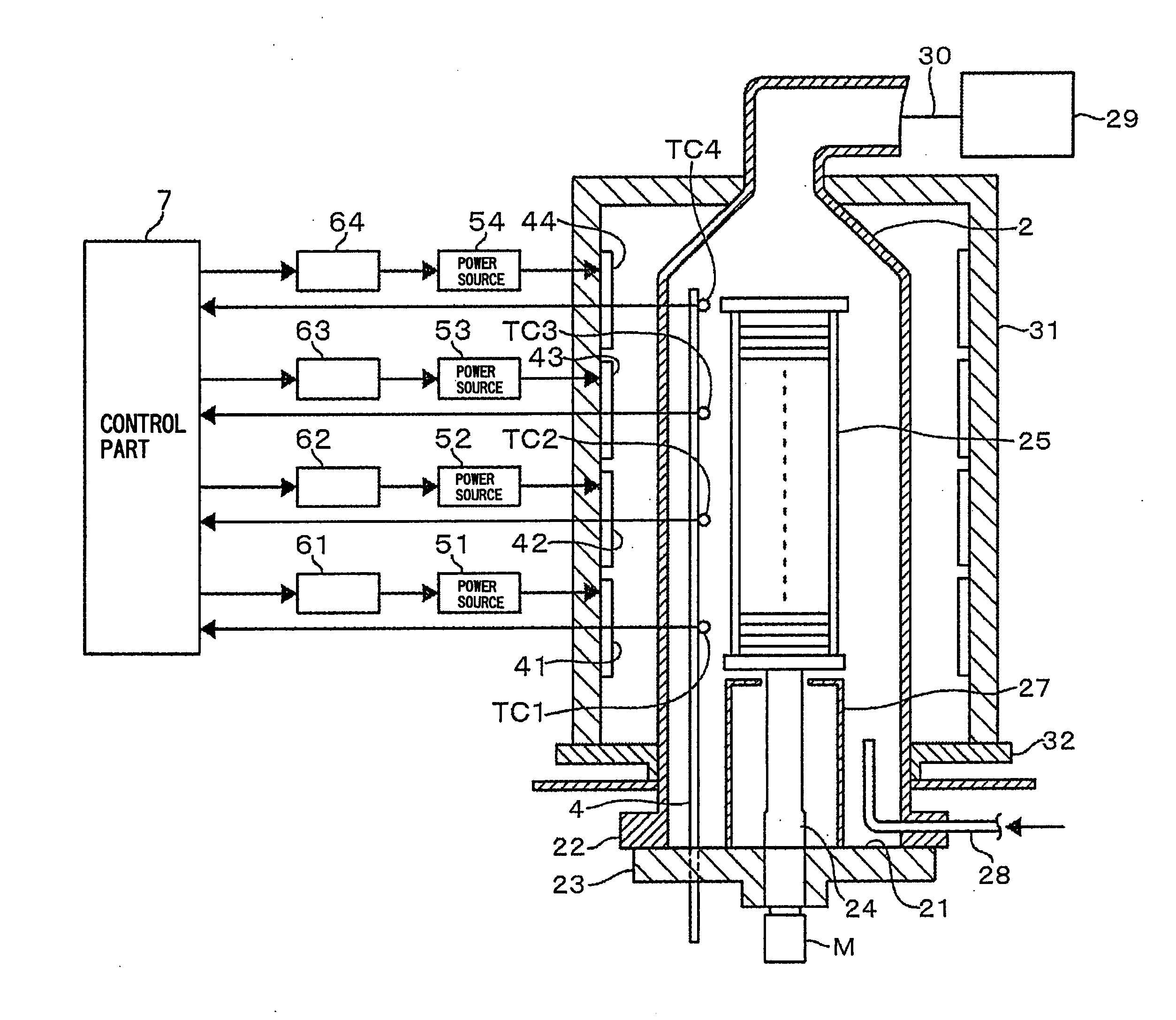
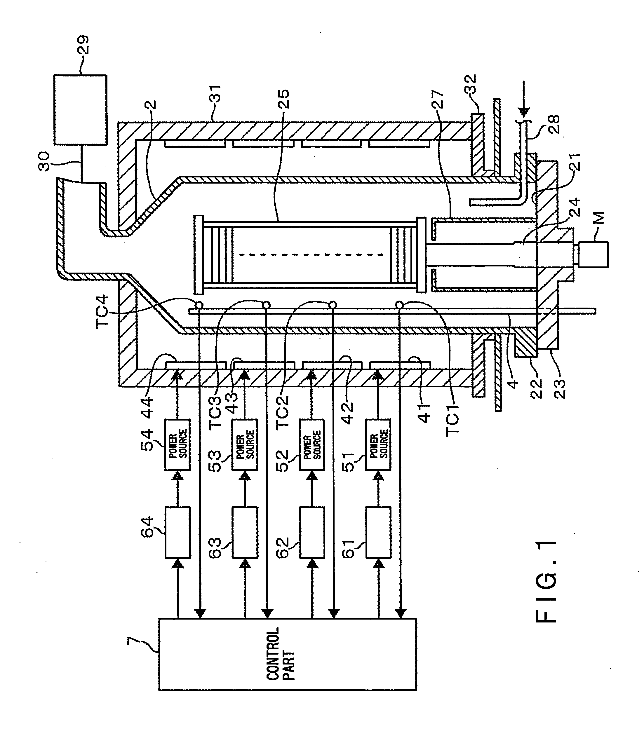
[0105]By using the above-described vertical heat processing apparatus, the wafer boat 25 holding dummy wafers was loaded into the reaction vessel 2, with setting a temperature of the heater at 300° C. With the lapse of time after loading of the wafer boat 25 into the reaction vessel 2, the temperature in the reaction vessel 2 became stabilized. Thereafter, a set temperature of the heater was raised up to 800° C. An inside of the reaction vessel 2 was a depressurized atmosphere of an inert gas. FIG. 13(a) shows temperature profiles obtained by the respective interior temperature sensors TC1 to TC4 after the first RUN. FIG. 13(b) shows temperature profiles which were obtained when auto-tuning was performed until the third RUN based on the flowchart shown in FIG. 5. By comparing FIG. 13(a) with FIG. 13(b), it can be seen that, as the number of times of RUN increased, the overshoot of the uppermost interior temperature sensor TC1 could be decreased and dispersion in the temperature prof...

example 2

[0106]A first RUN was performed under the same conditions as those of Example 1, other than a set temperature of the heater was 400° C. at the loading of the wafer boat 25 into the reaction vessel 2, and after the temperature in the reaction vessel 2 was stabilized, a set temperature of the heater was set up to 600° C. FIG. 14(a) shows temperature profiles obtained by the respective interior temperature sensors TC1 to TC4 after the first RUN was performed, and FIG. 14(b) shows the result after the fourth RUN was performed. By comparing FIG. 14(a) with FIG. 14(b), it can be seen that the overshoot amount of the uppermost interior temperature sensor TC1 after the first RUN could be decreased and dispersion in the temperature profiles between the zones could be also decreased.

example 3

[0107]A temperature of the heater was set at 400° C. at the loading of the wafer boat 25 into the reaction vessel 2, and after the temperature in the reaction vessel 2 was stabilized, a set temperature of the heater was set up to 760° C. Then, the auto-tuning was executed in the manner described in the embodiment. FIG. 15(a) shows an example of a temperature profile at this time in which the overshoot, the undershoot, and the recovery period converged with target values, while the temperature difference between the zones did not converge with a prescribed value range. FIG. 15(b) shows a temperature profile in which the temperature difference between the zones can fall within a prescribed value, after the tuning as show in FIG. 11 was performed. Also from this result, the inventors of the present invention believe that the steps shown in FIG. 11 are effective.


PUM


Abstract

A heat processing apparatus comprises: a reaction vessel; a heating unit disposed in the reaction vessel and configured to heat the processing region; a temperature detection part configured to detect a temperature of the processing region; and a control part configured to control the heating unit by a PID control. The control part includes: a rule table that is prepared such that predicted change amounts of a temperature property item when a temperature of the processing region is increased up to a target value, and change ratios of PID constants are correspondingly related to each other; a performance unit configured to repeatedly perform: a step of obtaining a temperature profile based on a temperature detected value of the temperature detection part and calculating a difference between an actually measured value and a target value of the temperature property item based on the temperature profile; and a step of, when the difference is over an allowable range and larger than a prescribed value, referring to the rule table and changing the PID constants to reset new PID constants by a change ratio corresponding to an predicted change amount of the temperature property item relative to the difference; until the difference can fall within the allowable range. The control part also includes an updating unit configured to update, when there is a difference between an actually measured change amount of the temperature property item with reference to the rule table and an predicted change amount of the temperature property item that has been predicted in the preceding cycle, the corresponding relationship between the PID constants and the predicted change amounts of the temperature property item described in the rule table, based on the actually measured change amount.

Description

CROSS REFERENCE TO RELATED APPLICATIONS[0001]This application is based upon and claims the benefit of priority from the prior Japanese Patent Application No. 2007-106247 filed on Apr. 13, 2007, the entire contents of which are incorporated herein by reference.FIELD OF THE INVENTION[0002]The present invention relates to, in an apparatus that thermally processes an object to be processed while controlling a temperature by a P (proportional element) I (Integral element) D (Derivative element) control, a technique for automatically tuning PID constants.DESCRIPTION OF RELATED ART[0003]There are heat processing apparatuses of a batch type and a wafer-fed type, among semiconductor manufacturing apparatuses. In these heat processing apparatuses, a processing region is divided into a plurality of zones, and a temperature in each zone is independently controlled. In a vertical heat processing apparatus, for example, an inside of a vertical reaction vessel is vertically divided into a pluralit...

Claims


Application Information

Patent Timeline
IPC IPC(8): G05B13/04H05B1/02G05D23/00
CPCG05D23/1935H01L21/67109H01L21/67248H01L22/00H01L21/324
Inventor TAKAHASHI, GOROINOUE, HISASHIKANDA, SHOICHIWANG, WENLING
Owner TOKYO ELECTRON LTD
Why Eureka
Try Eureka