Device and Method for Thread Positive Feeding

Inactive Publication Date: 2008-10-23
MEMMINGER IRO GMBH
View PDF4 Cites 13 Cited by
  • Summary
  • Abstract
  • Description
  • Claims
  • Application Information

AI Technical Summary

Benefits of technology

[0008]The goal of the invention is to present a system, as well as a method, with which thread-processing machines, especially cir

Problems solved by technology

Knitting machines used to create patterned goods cannot be supplied with thread with such positive feed w

Method used


Image

  • Device and Method for Thread Positive Feeding
  • Device and Method for Thread Positive Feeding
  • Device and Method for Thread Positive Feeding

Examples


Example

[0022]While the invention is susceptible of various modifications and alternative constructions, certain illustrated embodiments thereof have been shown in the drawings and will be described below in detail. It should be understood, however, that there is no intention to limit the invention to the specific forms disclosed, but on the contrary, the intention is to cover all modifications, alternative constructions and equivalents falling within the spirit and scope of the invention.

DETAILED DESCRIPTION OF THE PREFERRED EMBODIMENTS

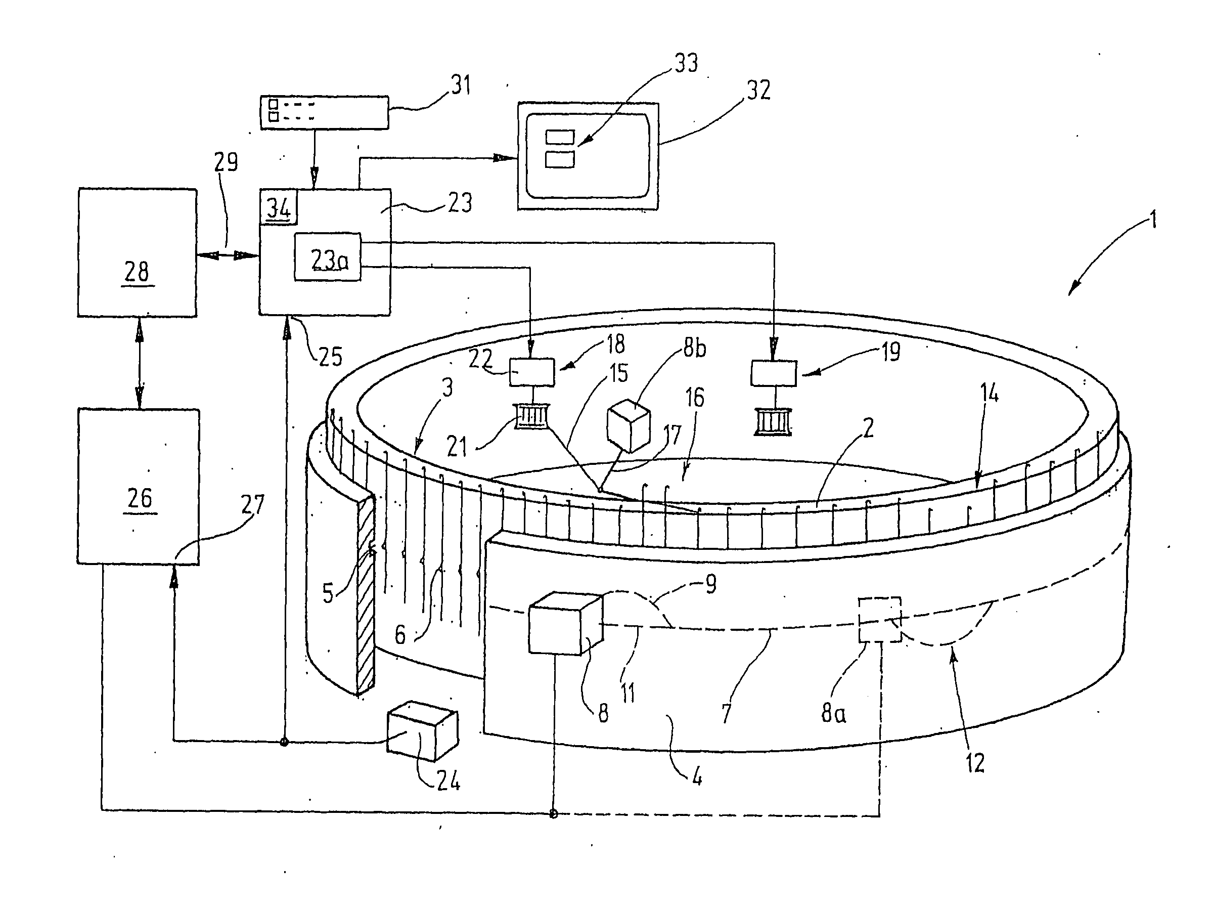
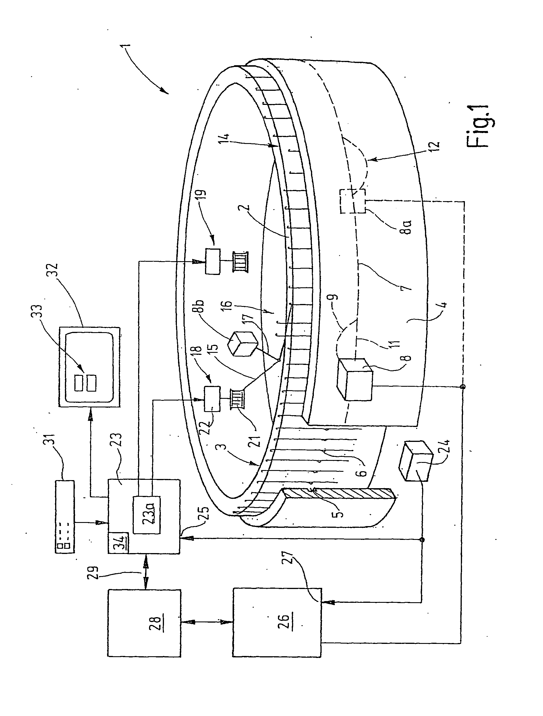
[0023]In the following description, a number of reference numbers are used to refer to specific elements in the several drawings. These reference numerals correspond to the drawing elements as follows: Knitting machine (1); Needle cylinder (2); Needles (3); Lock (4); Lock cam (5); Line (7); Switching element (8, 8a); Actuator (8b); Branches (v); Points (12); Stitching positions (14); Thread (15); Hold points (16); Thread guide (17); Thread feeding devices (1...


PUM

PropertyMeasurementUnit
Angleaaaaaaaaaa

Abstract

The invention relates to a control unit for thread feeding devices, such as those associated with knitting machines and the like. The control unit generates pattern or switch data control signals based on a pattern memory, or otherwise, for the thread feeding devices. In an embodiment of the invention, the control unit adds to or subtracts from the pattern data any advance or lag angles as necessary to account for the structure of the machine and to thus assure effective thread feeding.

Description

FIELD OF THE INVENTION[0001]The invention relates to a control device for at least one thread feeding device of a thread processing machine, especially a knitting machine. The invention also relates to a method for positive thread feeding to a textile machine, especially a knitting machine with changing thread requirements.BACKGROUND OF THE INVENTION[0002]Circular knitting machines and flat knitting machines are known, which are designed for stitching patterned goods. With respect to patterned goods, different stitching positions must be supplied with thread intermittently rather than continuously.[0003]One example of a circular knitting machine for creating patterned goods is seen in EP 0 724 033 A1. The circular knitting machine has a cutting device in order to cut away unnecessary thread. If thread of the corresponding color is needed again, the previously cut thread is fed again to the stitching position.[0004]In addition, a so-called striping attachment for a circular knitting ...

Claims


Application Information

Patent Timeline
IPC IPC(8): D04B15/48D04B15/66
CPCD04B15/48D04B15/66D04B15/99
Inventor WEBER, FRIEDRICH
Owner MEMMINGER IRO GMBH
Why Eureka
Try Eureka