Fuel vaporizer, method of installing the vaporizer, and fuel vaporizer system and method of controlling the system

Inactive Publication Date: 2008-10-23
THOMAS CHARLES W
View PDF11 Cites 18 Cited by
  • Summary
  • Abstract
  • Description
  • Claims
  • Application Information

AI Technical Summary

Benefits of technology

[0013]With its unique and novel features, the present invention provides an efficient and effective fuel vaporizer and

Problems solved by technology

Typically, an internal combustion engine may use only a portion of the fuel to drive the engine, and the r

Method used


Image

  • Fuel vaporizer, method of installing the vaporizer, and fuel vaporizer system and method of controlling the system
  • Fuel vaporizer, method of installing the vaporizer, and fuel vaporizer system and method of controlling the system
  • Fuel vaporizer, method of installing the vaporizer, and fuel vaporizer system and method of controlling the system

Examples


Example

[0026]Referring now to the drawings, FIGS. 1-8 illustrate some exemplary aspects the present invention.

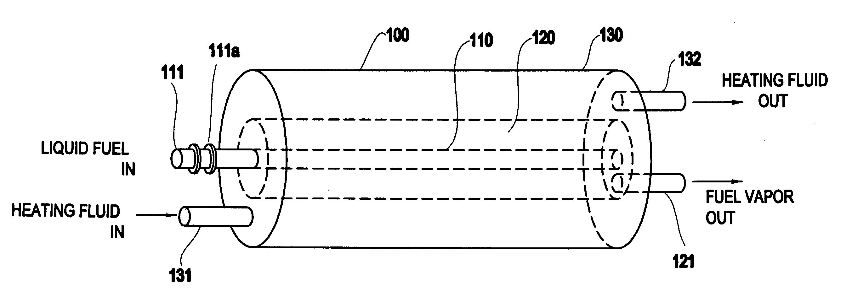
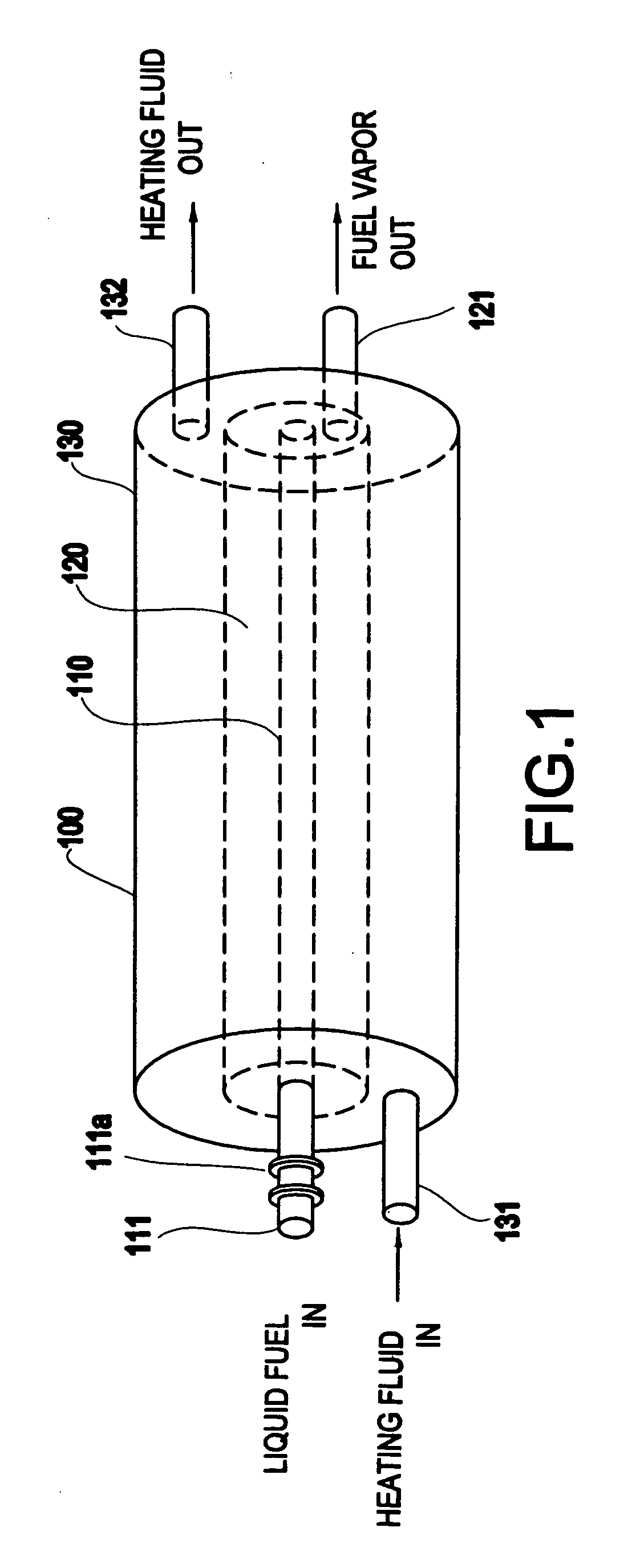
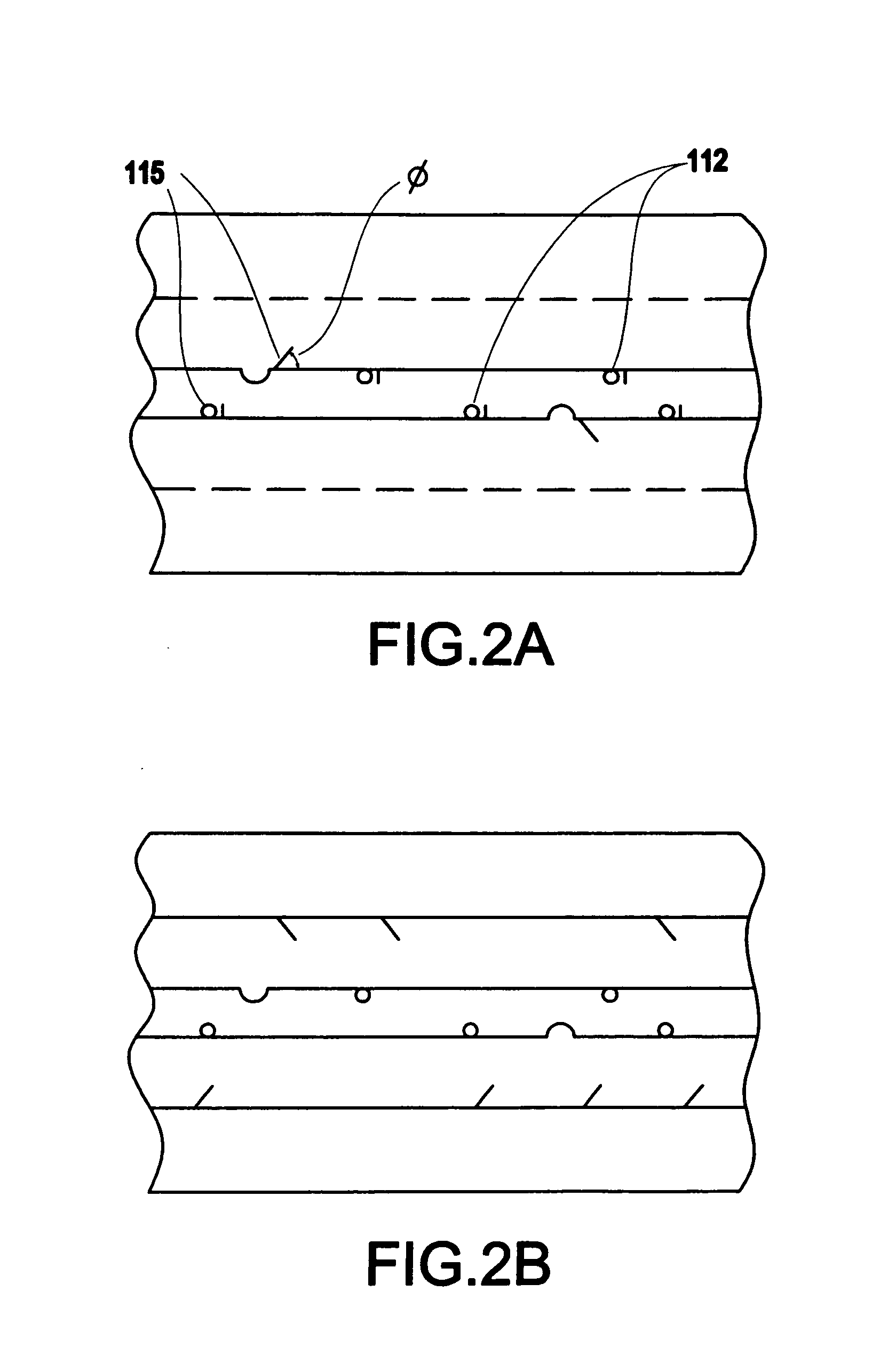
[0027]As illustrated, for example, in FIGS. 1-2B, a fuel vaporizer 100 may include an inner tube 110 (e.g., a cylindrical inner tube) including a liquid fuel inlet 111 for receiving liquid fuel and plural openings 112, a fuel vaporizing chamber 120 formed on the inner tube 110, and including a fuel vapor outlet 121 (e.g., through which fuel vapor exits), an outer housing 130 formed on the fuel vaporizing chamber 120, such that a reservoir is formed between the fuel vaporizing chamber 120 and the outer housing 130, and a heating fluid inlet 131 and heating fluid outlet 132 which are connected to the outer housing 130.

[0028]For example, the liquid fuel (e.g., gasoline, gasoline / ethanol mix, ethanol, diesel, biodiesel, etc.) may exit the inner tube 110 and enter the fuel vaporizing chamber 120 through the plural openings, the liquid fuel may be vaporized to fuel vapor in the fuel vapo...


PUM

PropertyMeasurementUnit
Angleaaaaaaaaaa
Angleaaaaaaaaaa
Lengthaaaaaaaaaa

Abstract

A fuel vaporizer includes an inner tube including a liquid fuel inlet for receiving liquid fuel and plural openings, a fuel vaporizing chamber formed on the inner tube, and comprising a fuel vapor outlet, an outer housing formed on the fuel vaporizing chamber, such that a reservoir is formed between the fuel vaporizing chamber and the outer housing, and a heating fluid inlet and heating fluid outlet which are connected to the outer housing.

Description

BACKGROUND OF THE INVENTION[0001]1. Field of the Invention[0002]The present invention relates to a fuel vaporizer and a fuel vaporizer system, and more particularly, to a fuel vaporizer which includes an inner tube with plural openings, and a fuel vaporizing chamber formed on the inner tube.[0003]2. Description of the Related Art[0004]Typically, an internal combustion engine may use only a portion of the fuel to drive the engine, and the remainder is lost to emissions. Thus, these engines could be more fuel efficient.[0005]It has been suggested that fuel efficiency could be improved by vaporizing the fuel before introducing the fuel into the combustion chamber of the engine. Several attempts have been made to provide an efficient fuel vaporizer.[0006]However, such conventional fuel vaporizers are cumbersome and / or ineffective.SUMMARY OF THE INVENTION[0007]In view of the foregoing and other problems, disadvantages, and drawbacks of the related art, a purpose of the exemplary aspects ...

Claims


Application Information

Patent Timeline
IPC IPC(8): F02M31/18
CPCF02M31/18Y10T29/49361Y02T10/126Y02T10/12
Inventor THOMAS, CHARLES W.
Owner THOMAS CHARLES W
Why Eureka
Try Eureka