Apparatus, system, and method for in-situ extraction of hydrocarbons

a hydrocarbon extraction and apparatus technology, applied in the field of hydrocarbon reservoir recovery, can solve the problems of high cost of flushing process, large amount of thermal energy to be injected into oil shale, etc., and achieve the effect of efficient delivery of thermal energy

Inactive Publication Date: 2008-10-23
SHURTLEFF J KEVIN +1
View PDF105 Cites 29 Cited by
  • Summary
  • Abstract
  • Description
  • Claims
  • Application Information

AI Technical Summary

Benefits of technology

[0017]From the foregoing, the Applicant asserts that a need exists for a system, method, and apparatus for recycling thermal energy contained within a formation for use in subsequent formations. Beneficially, such an apparatus, system and method should efficiently deliver thermal energy from hydrocarbon bearing formations which vary in depth from surface formations to formations buried over 3000 ft deep. Further benefits of the apparatus, system and method include utilizing a process that economically and environmentally seals a depleted formation.
[0023]In certain embodiments the method includes injecting the thermal conduit fluid by passing the thermal conduit fluid through an injection tube. The diameter of the injection tube is proportioned to increase velocity of the thermal conduit fluid and to reduce residence time of the thermal conduit fluid within the injection tube. In certain embodiments the diameter of the injection tube is between about 1 inch and about 2 inches. In one embodiment, the diameter of the injection tube is between 1 inch and 1.66 inches.
[0025]A system for extracting hydrocarbons is disclosed which includes at least one well drilled through an hydrocarbon bearing formation. A completion unit is configured to position an injection tube near a fluid injection point and a production tube near a production point. A heat source is configured to heat a thermal conduit fluid to a temperature selected to pyrolyze the hydrocarbon. An injection unit heats the target zone by circulating the thermal conduit fluid through the target zone. The thermal conduit fluid sweeps a hydrogen rich product of the pyrolyzation reaction into the production tube leaving a hydrogen poor product of the pyrolyzation reaction in the target zone. A combustion unit is configured to inject an oxygen mixture into the target zone and combust the hydrogen poor product which in turn heats the oxygen mixture. A cooling unit is configured to pump a cool gas stream into the target zone to absorb residual heat from the hydrocarbon formation. A recycling unit is configured to recycle the heat absorbed by the cool gas stream to heat an adjacent well. The system further discloses an abandonment unit that injects a solution of sodium bentonite and water under high pressure into the target zone. The sodium bentonite and water solution seals the depleted hydrocarbon formation with the sodium bentonite and water solution to prevent intrusion and contamination of groundwater in the target zone.

Problems solved by technology

Second, a huge amount of thermal energy must be injected into the oil shale.
Such processes are energy intensive and require the drilling of multiple wells to recover kerogen from a relatively small section of the formation.
Any of the mining processes introduce a number of environmental issues, including disposal of solvents, recovery of the mined land, and disposal of the shale remainder after the bulk of the hydrocarbons are removed.
The flushing process is expensive because of the fluid costs, and can only recover fluids that are essentially low viscosity although perhaps a bit higher viscosity than the oil recovered in the primary recovery.
The flushing process is also subject to channeling between wells which can prevent full recovery of oil; channeling can be mitigated with fluid loss additives but these introduce damage into the formation.
Further, some formations are sensitive to the introduction of water (e.g. formations with a high clay content) and therefore the flushing process is either ineffective or requires expensive anti-swelling additives to the fluid.
The flame recovery process is difficult to initiate and control, it inherently consumes some of the oil in the formation, and it introduces combustion byproducts into the final produced fluids.
Whether the produced fluids are burned or utilized as a product for sale, the changing of the molecular composition of the produced fluids introduces complications that must be managed.
With the current technologies no method, system or apparatus has been proposed to capture the thermal energy of a heated formation.
Thus, a large amount of thermal energy is wasted with the current technologies.
Additionally, inefficient injection methods and injection tubing used in the present technologies results in additional heat being lost to the surrounding formation.
With the deposits varying in depth from surface exposures to layers buried over 3000 ft deep, heat transferring apparatuses of the current technologies are inefficient, allowing thermal energy loss to the layers of rock deposited on top of the formation.

Method used


Image

  • Apparatus, system, and method for in-situ extraction of hydrocarbons
  • Apparatus, system, and method for in-situ extraction of hydrocarbons
  • Apparatus, system, and method for in-situ extraction of hydrocarbons

Examples


Embodiment Construction

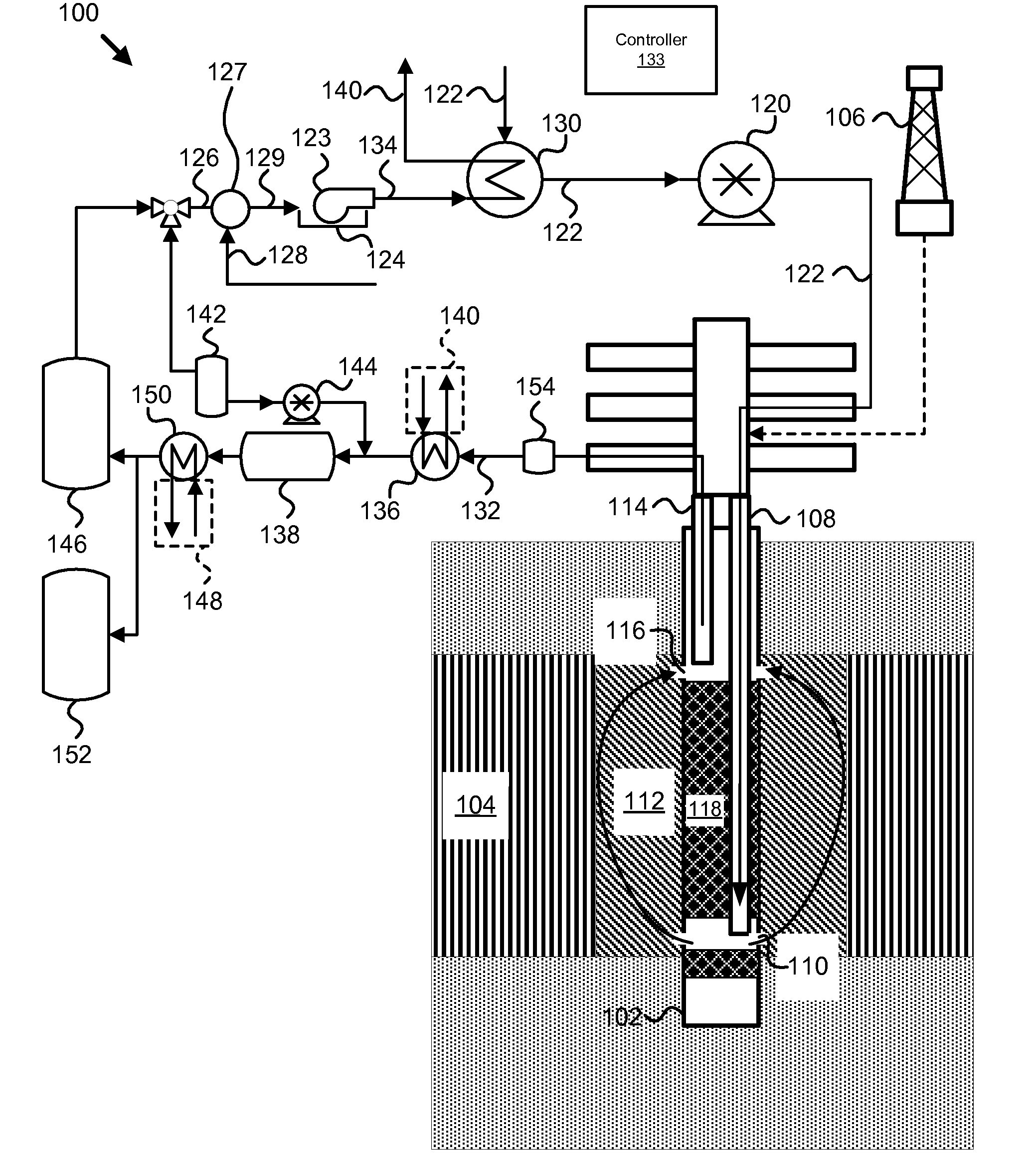
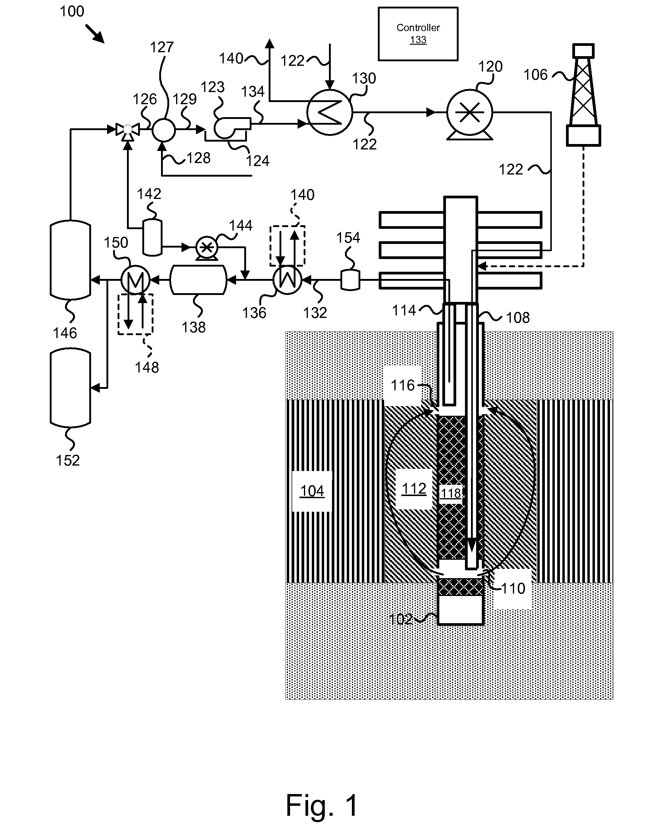
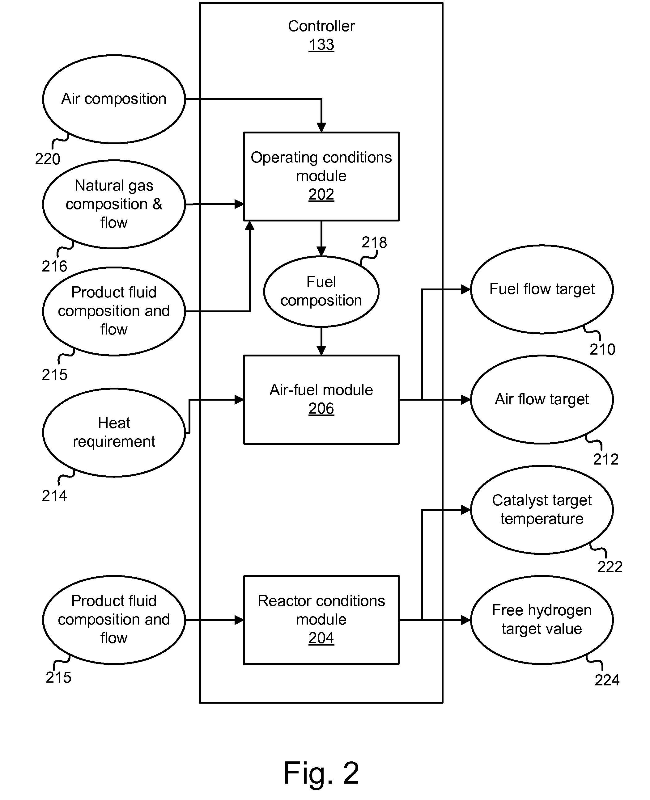
[0043]It will be readily understood that the components of the present invention, as generally described and illustrated in the figures herein, may be arranged and designed in a wide variety of different configurations. Thus, the following more detailed description of the embodiments of the apparatus, system, and method of the present invention, as presented in FIGS. 1 through 15, is not intended to limit the scope of the invention, as claimed, but is merely representative of selected embodiments of the invention. Some aspects of the present invention may be more fully understood in light of U.S. Provisional Patent Application No. 60 / 912,354 to J. Kevin Shurtleff entitled “Apparatus, system, and method for in-situ extraction of oil from oil shale,” filed on Apr. 17, 2007, incorporated herein by reference. Additionally, some aspects of the present invention may be more fully understood in light of U.S. patent application Ser. No. 11 / 782,463 to J. Kevin Shurtleff entitled “Apparatus, ...


PUM


Abstract

An apparatus, system, and method are disclosed for in-situ extraction of hydrocarbons from a hydrocarbon bearing formation. The system includes a well drilled through a hydrocarbon bearing formation, and a completion unit that places an injection tube near a fluid injection of a target zone and a production tube near a fluid production point of the target zone. The injection tube comprising a tube with an inner diameter between about 1 inch and about 2 inches. The system includes a heat source, and a thermal conduit fluid that delivers heat from the heat source to the target zone. A mixer mixes an oxygen mixture and an injection unit injects the oxygen mixture into the depleted target zone to combust a coke remainder within the target zone. The system further includes a recycling unit configured to circulate a cool gas through the heated target zone to absorb the thermal energy disposed in the heated target zone.

Description

CROSS-REFERENCES TO RELATED APPLICATIONS[0001]This application claims the benefit of U.S. Provisional Patent Application No. 60 / 912,354 entitled “Apparatus, system, and method for in-situ extraction of oil from oil shale” and filed on Apr. 17, 2007 for Kevin Shurtleff and Stewart Cowley which is incorporated herein by reference. In addition, this application claims the benefit of U.S. patent application Ser. No. 11 / 782,463 entitled “Apparatus, system, and method for in-situ extraction of hydrocarbons” and filed on Jul. 24, 2007 for Kevin Shurtleff, which claims the benefit of U.S. Provisional Patent Application No. 60 / 820,256 entitled “Apparatus, system, and method for in-situ extraction of oil from oil shale” and filed on Jul. 25, 2006 for Kevin Shurtleff, both of which are incorporated herein by reference. This application also claims the benefit of U.S. Provisional Patent Application No. 60 / 981,027 entitled “Apparatus, system, and method for single well gas stimulation for enhanc...

Claims


Application Information

Patent Timeline
Patent Type & Authority Applications(United States)
IPC IPC(8): E21B43/24
CPCE21B43/24
Inventor SHURTLEFF, J. KEVINCOWLEY, STEWART
Owner SHURTLEFF J KEVIN
Why Eureka
Try Eureka