Multifunctional rotary switch

a multi-functional, rotary switch technology, applied in the field of rotary switches, can solve the problems of increasing the size of the display of electronic devices, driver distraction, and complex electronic devices being integrated into the dashboard of vehicles, and achieve the effect of facilitating the arrangement of the arrangement and high degree of functionality

Active Publication Date: 2008-10-23
HARMAN BECKER AUTOMOTIVE SYST
View PDF6 Cites 36 Cited by
  • Summary
  • Abstract
  • Description
  • Claims
  • Application Information

AI Technical Summary

Benefits of technology

[0010]The rotary switch may be designed to be very compact while providing a high degree of functionality. The functions that are associated with a certain mode of operation can be chosen depending on the electronic device that the switch is to operate. For example, the rotational mode of operation could be used to change the volume of an audio device, to scroll through songs on a play list of a music player or to scroll through the functions of a menu, while the translational mode of operation could be used to skip between songs of a play list, or to bring up different menus, or to skip between locations when used to control a navigational device, while the pushing mode of operation could be used to select a song, to select a navigational target, or to select a function from a menu, or the like. Since, for example, an audio device and a nav

Problems solved by technology

Recently, complex electronic devices are being integrated into the dashboards of vehicles.
On the other hand, a need exists for displaying more information related to the electronic devices, which results in an inc

Method used


Image

  • Multifunctional rotary switch
  • Multifunctional rotary switch
  • Multifunctional rotary switch

Examples


Embodiment Construction

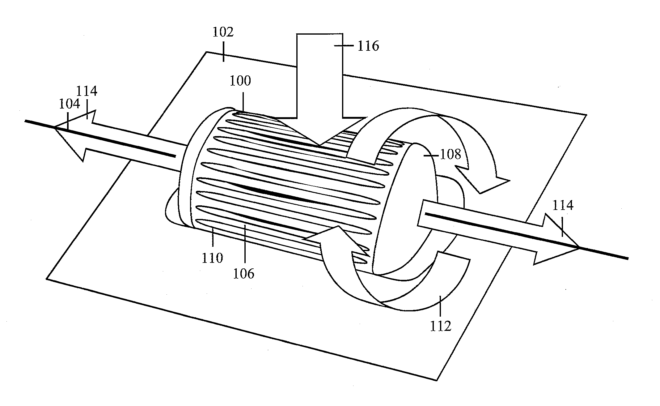
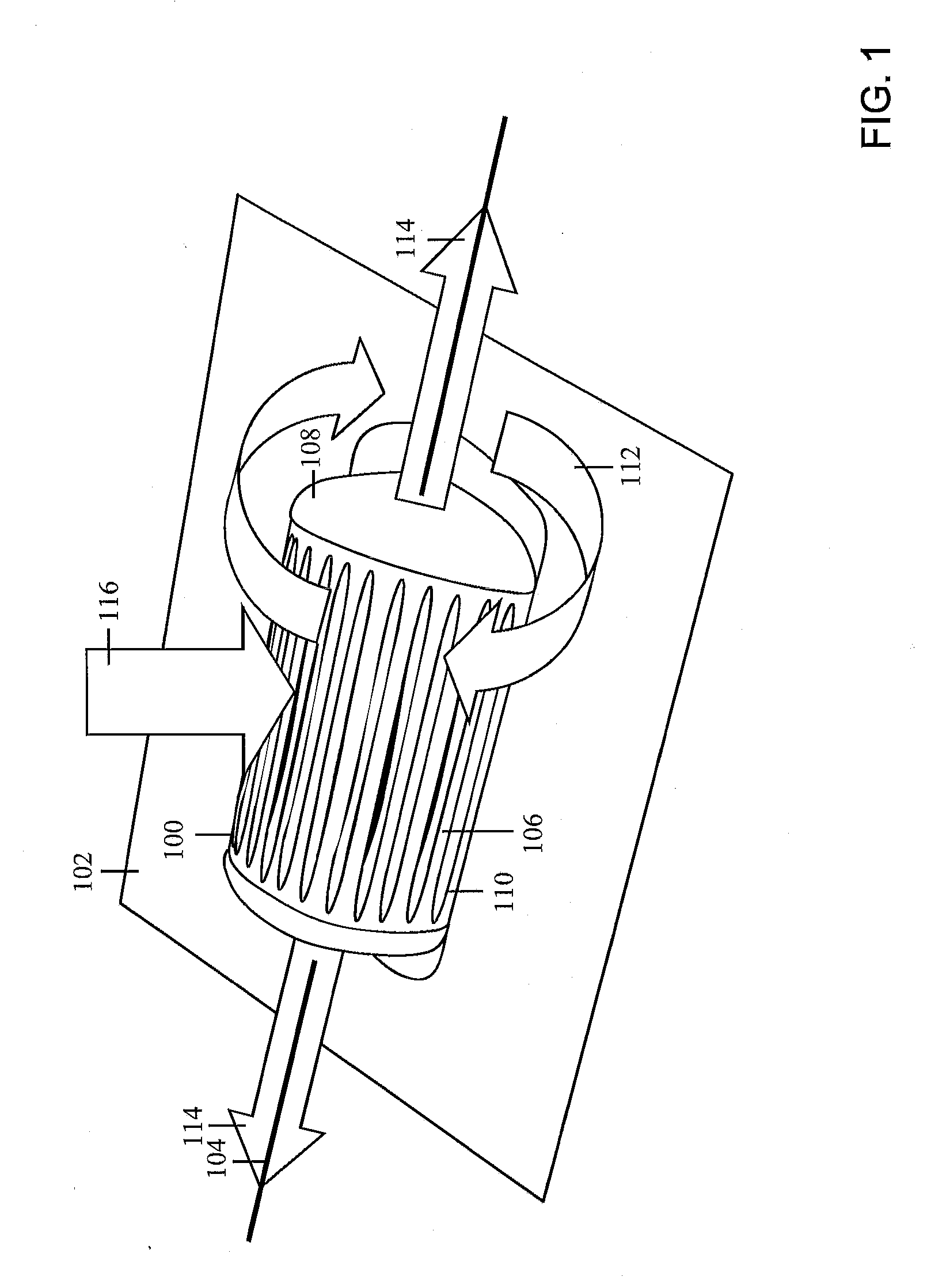
[0017]FIG. 1 shows one example of an implementation of a multifunctional rotary switch 100 mounted to the surface or plate 102 of a component. The component could be any electronic device, such as an audio device, or simply a surface for control elements of an electronic device. For example, the multifunctional rotary switch 100 may be mounted on a front surface inside a vehicle. The front surface could be a face plate of a navigational device or of an audio device. It may also be another vehicle component such as a dashboard, a steering wheel, a door or a center console. The multifunctional rotary switch 100 can be mounted in such a way that the axis of rotation of the roller is in the same plane as the surface, or it could be mounted such that the axis of rotation lies above or below the surface. Depending on the position of the axis of rotation, a different fraction of the circumferential face of the roller is exposed. The position of the axis of rotation can be chosen in accorda...


PUM


Abstract

A multifunctional rotary switch for operating an electronic device is providing having a roller with an axis of rotation. The roller has a bidirectional rotational mode of operation where the roller rotates in both a clockwise and counter clockwise direction around the axis, a translational mode of operation where the roller is moved in a direction substantially parallel to the axis of rotation and a pushing mode of operation where the roller is moved in a direction substantially perpendicular to the axis of rotation.

Description

RELATED APPLICATIONS[0001]This application claims priority of European Patent Application Serial Number 07 008 116.1, filed on Apr. 20, 2007, titled MULTIFUNCTION ROTARY SWITCH, which application is incorporated in its entirety by reference in this application.BACKGROUND OF THE INVENTION[0002]1. Field of the Invention[0003]The invention relates to a rotary switch with added functionality. In particular, the invention relates to a rotary switch that apart from its rotary mode of operation includes a translational mode of operation and a pushing mode of operation.[0004]2. Related Art[0005]Recently, complex electronic devices are being integrated into the dashboards of vehicles. These electronic devices provide a variety of functions, which results in the need for a multitude of control elements for executing these functions. Control elements presently used include switches, rockers, knobs, push buttons and the like. On the other hand, a need exists for displaying more information rela...

Claims


Application Information

Patent Timeline
IPC IPC(8): H01H19/14
CPCH01H25/008H01H2019/146G05G9/047H01H19/10H01H19/14
Inventor WLOTZKA, PAUL
Owner HARMAN BECKER AUTOMOTIVE SYST
Why Eureka
Try Eureka