Inverter topology for an electric motor

a topology and electric motor technology, applied in the direction of electronic commutation motor control, motor/generator/converter stopper, dynamo-electric converter control, etc., can solve the problems of additional magnets, additional dc voltage burden, and motor requires additional spa

Inactive Publication Date: 2008-10-23
GM GLOBAL TECH OPERATIONS LLC
View PDF9 Cites 31 Cited by
  • Summary
  • Abstract
  • Description
  • Claims
  • Application Information

AI Technical Summary

Problems solved by technology

However, a larger motor requires additional space, additional magnets provide additional complexity, and boosting the available DC voltage burdens the motor with a higher current rating.
However, even this conventional inverter topology has limitations on the ability to increase available power and / or decrease the current rating.

Method used


Image

  • Inverter topology for an electric motor
  • Inverter topology for an electric motor
  • Inverter topology for an electric motor

Examples


Embodiment Construction

[0011]The following detailed description is merely exemplary in nature and is not intended to limit the invention or the application and uses of the invention. Furthermore, there is no intention to be bound by any expressed or implied theory presented in the preceding technical field, background, brief summary or the following detailed description.

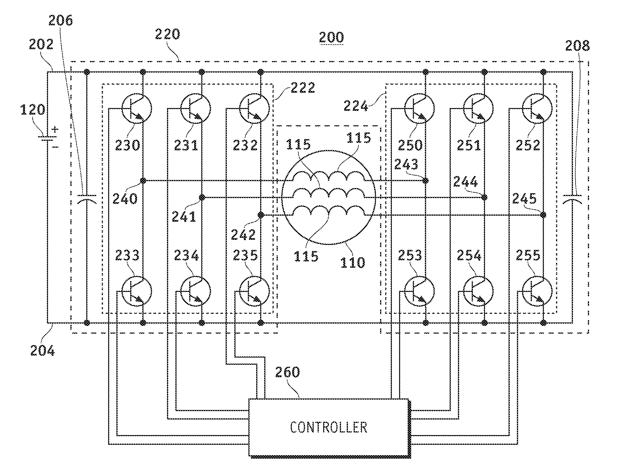
[0012]Referring to FIG. 1, a conventional inverter 100 for a wye-connected three-phase electric motor 110 is connected between lines 115 of the motor 110 and a power source 120. This conventional inverter topology utilizes a six-switch inverter 100 including transistors 130 to 135, such as Insulated Gate Bipolar Transistors (IGBT), operating in response to signals from a controller (not shown) to provide a direct current (DC) link across a line-to-line portion of the motor 110.

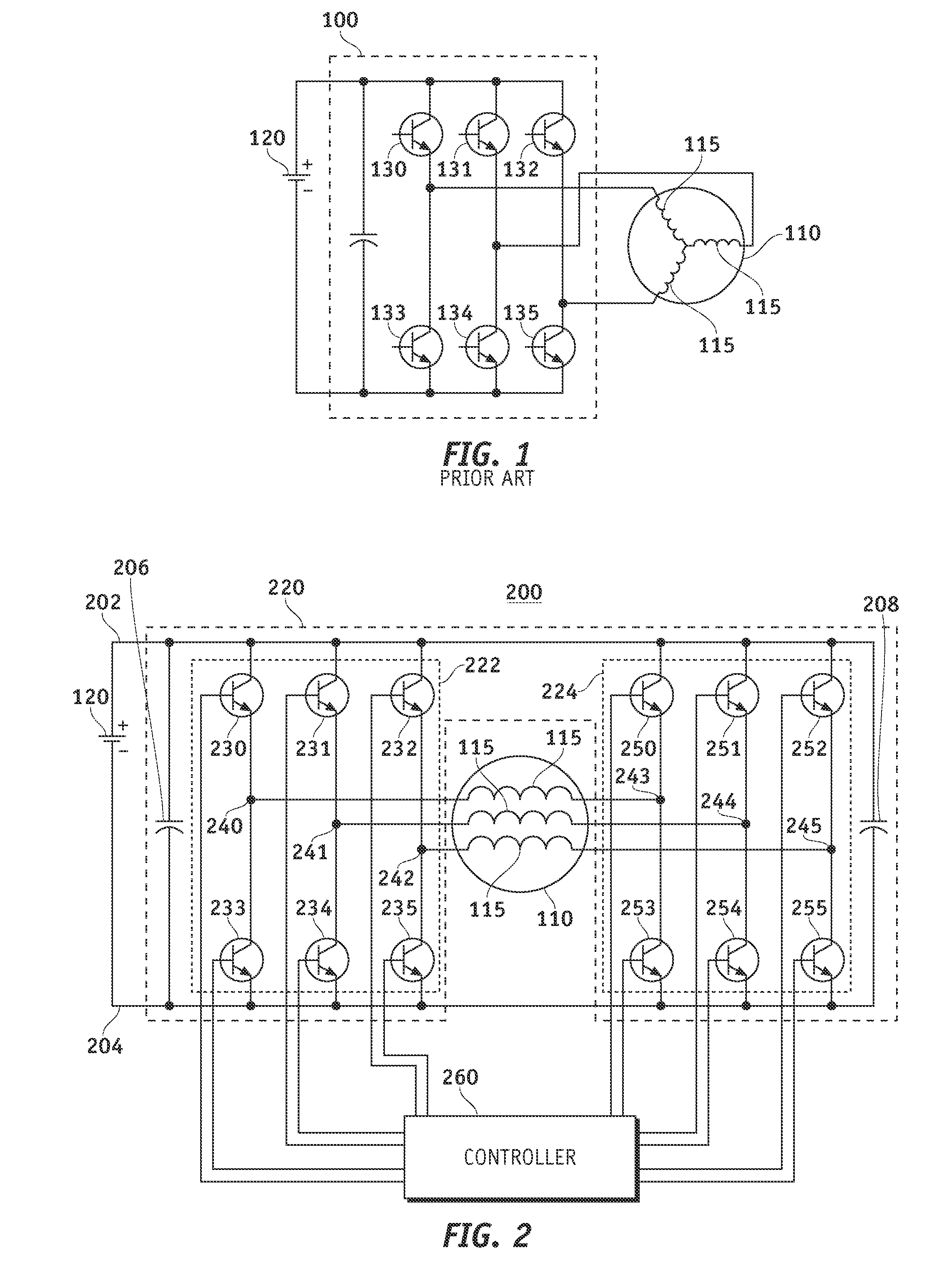
[0013]FIG. 2 depicts an electric motor system 200 including a six-leg inverter 220 coupled to an open end-winding three-phase alternating current (AC) motor 110 wher...


PUM


Abstract

An inverter is provided for controlling application of voltage from a power source to a motor having a plurality of windings. The inverter includes a first set of one or more switching elements and a second set of one or more switching elements. The first and second sets of one or more switching elements are connected between a high voltage side and a low voltage side of the power source. Each of the first set of one or more switching elements is connected to one of a first set of nodes, where each of the first set of nodes is connected to a first winding end of one of the plurality of windings of the motor. Each of the second set of one or more switching elements is connected to one of a second set of nodes and each of the second set of nodes is connected to a second winding end of one of the plurality of windings.

Description

TECHNICAL FIELD[0001]The present invention generally relates to electric motors, and more particularly relates to electric motor inverters.BACKGROUND OF THE INVENTION[0002]In a DC-driven electric motor system, such as a hybrid system with one or more motors, the power of the system is typically increased by enlarging the motor, adding additional magnets to the motor, or boosting the available DC voltage with, for example, a conventional boost DC-DC converter. However, a larger motor requires additional space, additional magnets provide additional complexity, and boosting the available DC voltage burdens the motor with a higher current rating.[0003]Alternatively, an inverter can be provided to obtain increased power from an electric motor system. A conventional six-switch, three-leg inverter topology can be provided to increase the power of a system which includes one or more three-phase motors where the DC link is connected across a line-to-line portion of the wye-connected three-ph...

Claims


Application Information

Patent Timeline
Patent Type & Authority Applications(United States)
IPC IPC(8): H02P7/06
CPCH02P25/22H02P27/08
Inventor NAGASHIMA, JAMES M.WELCHKO, BRIAN ASAVAGIAN, PETER J.
Owner GM GLOBAL TECH OPERATIONS LLC
Why Eureka
Try Eureka