Zero-voltage soft switch topological main circuit of arc welding inverter

A soft-switching and inverter technology, applied in arc welding equipment, adjusting electrical variables, high-efficiency power electronic conversion, etc., can solve problems such as increasing circuit circulation, damage, and reducing power factor.

Inactive Publication Date: 2009-04-22
JIANGSU UNIV OF SCI & TECH
View PDF0 Cites 16 Cited by
  • Summary
  • Abstract
  • Description
  • Claims
  • Application Information

AI Technical Summary

Problems solved by technology

[0008] The purpose of the present invention is to address the deficiencies of the prior art, to provide an arc welding inverter topology main circuit that can make the high-power switching tube realize soft switching under no-load, light-load and heavy-load conditions, which can solve the problem of auxiliary inductance The problem of increasing the circuit circulation, reducing the power factor and often being damaged when the current is high

Method used


Image

  • Zero-voltage soft switch topological main circuit of arc welding inverter
  • Zero-voltage soft switch topological main circuit of arc welding inverter
  • Zero-voltage soft switch topological main circuit of arc welding inverter

Examples


Embodiment 1

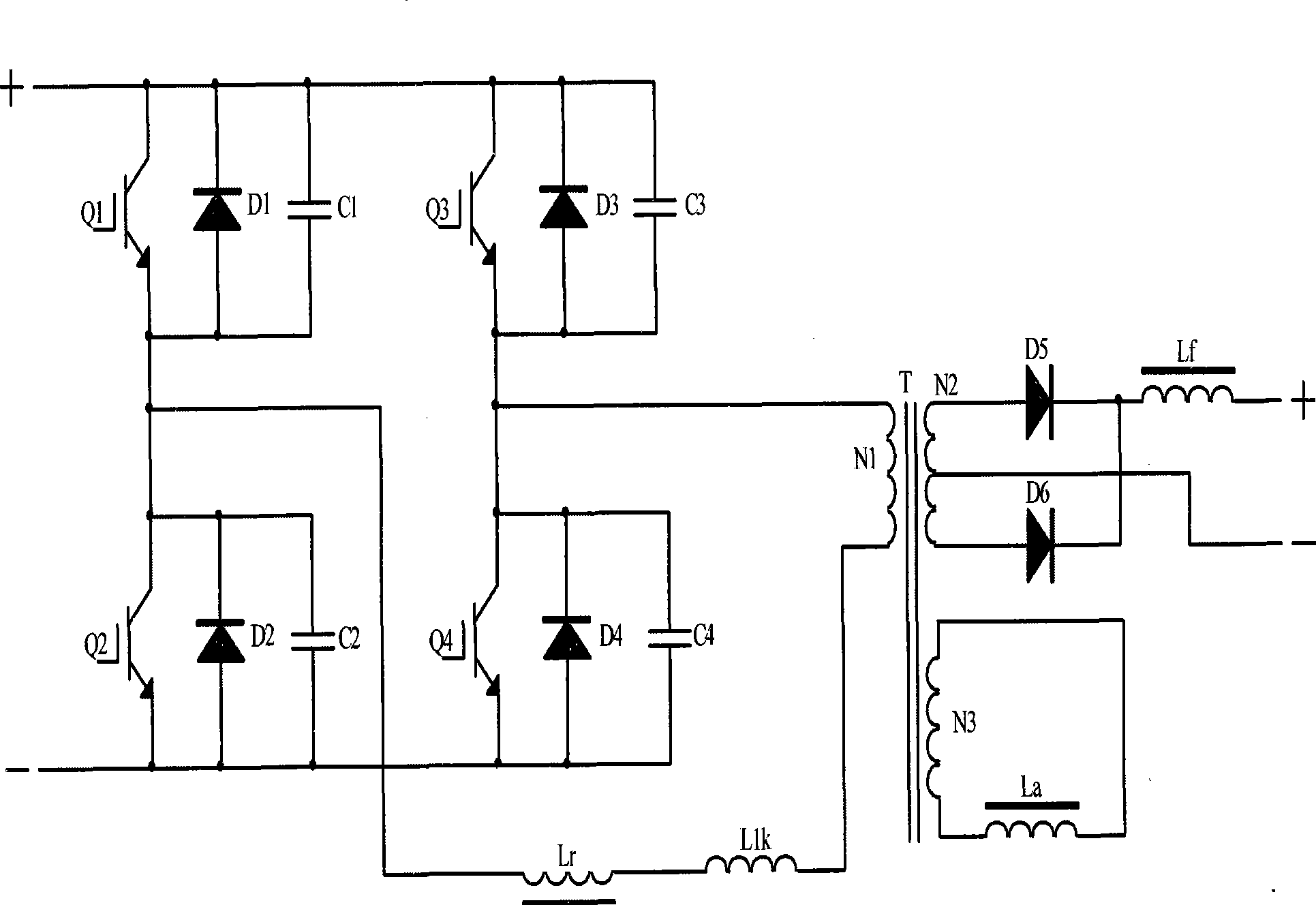
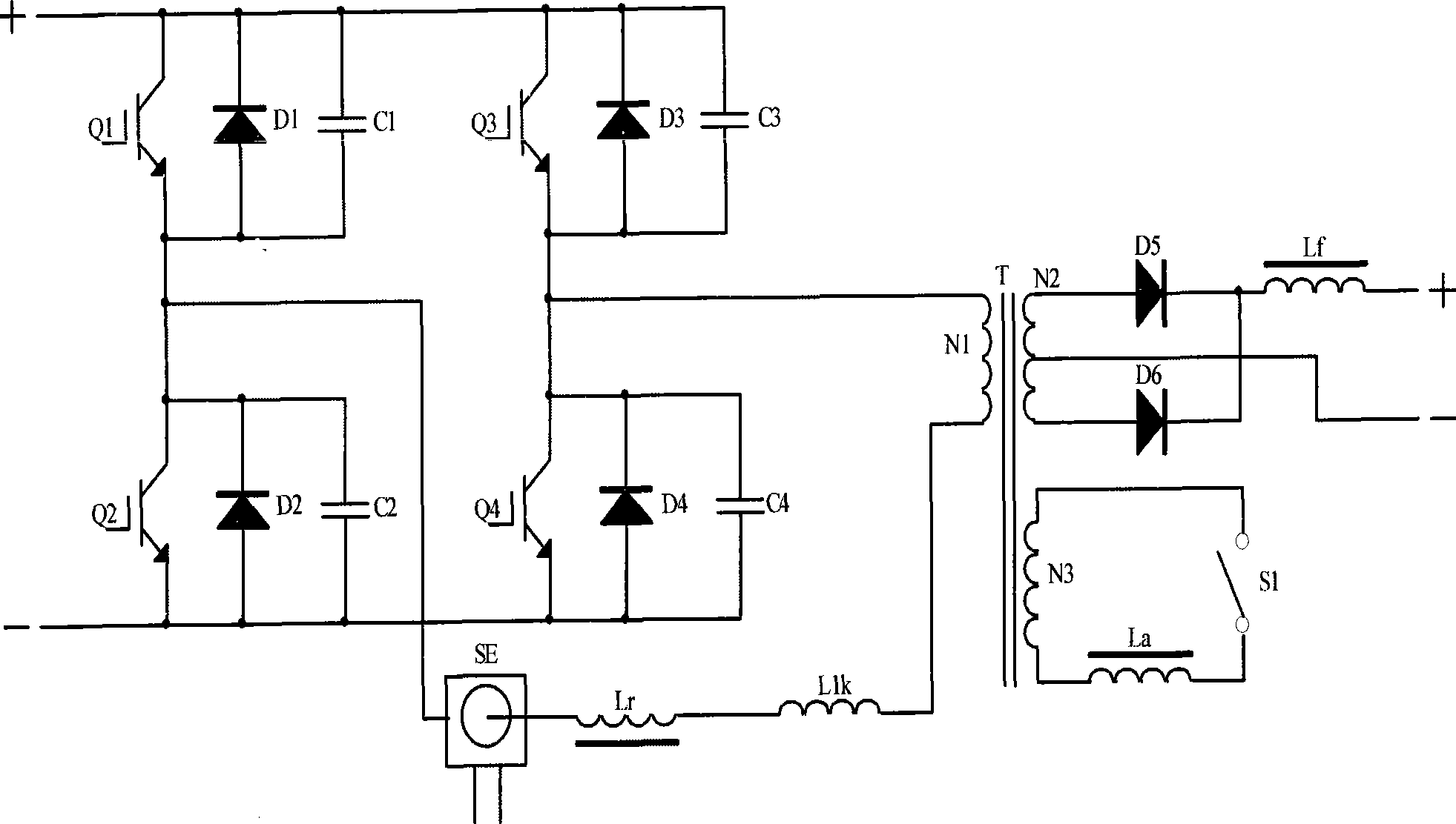
[0021] Such as image 3 As shown, the full-bridge phase-shifting resonant circuit of the present invention is the same as the above-mentioned circuit. An auxiliary coil N3 is connected in parallel on the secondary side of the high-frequency transformer T, the auxiliary coil N3 is connected to the auxiliary inductance La, and the auxiliary inductance La is connected in series with the electronic switch S1, the electronic switch S1 is connected to the control circuit and is sampled by the current sampling coil SE The primary side current of the high-frequency transformer T realizes that the present invention is turned off under heavy load, and turned on under no-load and light-load states.

Embodiment 2

[0023] Such as Figure 4 As shown, the full-bridge phase-shifting resonant circuit of the present invention is the same as the above-mentioned circuit. An auxiliary coil N3 is connected in parallel to the primary side of the high-frequency transformer T, the auxiliary coil N3 is connected to the auxiliary inductance La, and the auxiliary inductance La is connected in series with the electronic switch S1, the electronic switch S1 is connected to the control circuit and is sampled by the current sampling coil SE The primary side current of the high-frequency transformer T realizes that the present invention is turned off under heavy load, and turned on under no-load and light-load states.

Embodiment 3

[0025] Such as Figure 5 As shown, the full-bridge phase-shifting resonant circuit of the present invention is the same as the above-mentioned circuit. The auxiliary inductor La is directly connected in series with the electronic switch S1 and then connected to the secondary winding N2 of the high frequency transformer T. The electronic switch S1 is connected to the control circuit and samples the primary current of the high-frequency transformer T through the current sampling coil SE, so that the present invention can be turned off under heavy load and turned on under no-load and light-load conditions.


PUM


Abstract

The invention discloses a topology main circuit of a zero-voltage soft switching arc welding inverter, which comprises a leading leg, a lagging leg and a full-bridge phase-shifting resonance circuit. The leading leg and the lagging leg are formed by high-power insulated gate bipolar transistors; the full-bridge phase-shifting resonance circuit consists of inverse parallel diodes of the transistors and parallel capacitors of the transistors; the full-bridge phase-shifting resonance circuit is accessed to a primary side of a high-frequency transformer through a resonance inductance and leakage inductance; a secondary winding of the high-frequency transformer outputs inverted power supply; the front end of the resonance inductance is connected with a current sampling winding in series; the secondary inductance is connected with the winding of the high-frequency transformer after the secondary inductance is connected with an electric switch; and the electric switch is connected with a control circuit, and samples primary current of the high-frequency transformer through the current sampling winding. The topology main circuit realizes switching of the electric switch by the control circuit, can increase the primary current value of the transformer by opening the electric switch under idle load and light load, and can reduce circulating current of the circuit and increase power factor by cutting off the electric switch during over loading, thereby avoiding a magnetic core heating severely so as to damage elements and devices, and realizing zero-voltage switching of all main power devices in a loading range.

Description

technical field [0001] The invention relates to a welding device for welding metal, in particular to a topological main circuit of an arc welding machine. Background technique [0002] At present, the full-bridge zero-voltage soft switching (FB-ZVS) topology main circuit and pulse width modulation (PWM) are usually used in arc welding inverters to realize zero-voltage switching of high-power switching tubes. Such as figure 1 As shown, Q1 and Q2 are ahead of Q3 and Q4 by one phase respectively, and the bridge arm composed of Q1 and Q2 is called the leading arm, and the bridge arm composed of Q3 and Q4 is called the lagging arm. The two power devices of each bridge arm conduct 180° complementary conduction, and there is a dead time between them, that is, the time when the two transistors are not conducting, and the conduction angle of the two bridge arms differs by one phase, that is, phase shifting Angle, by adjusting the phase shift angle to achieve pulse width modulation,...

Claims


Application Information

Patent Timeline
Patent Type & Authority Applications(China)
IPC IPC(8): B23K9/10H02M3/335
CPCY02B70/1433Y02B70/1491Y02B70/10Y02P70/10Y02P80/10
Inventor 方臣富黄隽孟有明
Owner JIANGSU UNIV OF SCI & TECH
Why Eureka
Try Eureka