Elastic wave filter

Active Publication Date: 2008-10-23
MURATA MFG CO LTD
View PDF11 Cites 7 Cited by
  • Summary
  • Abstract
  • Description
  • Claims
  • Application Information

AI Technical Summary

Benefits of technology

[0012]To overcome the problems described above, preferred embodiments of the present invention provide a resonator-type elastic wave filter capable of sufficiently increasing an attenuation amount near the passband without increasing the chip size.
[0023]Moreover, as is known, the magnitude of the electromechanical coefficient K2 and the sound velocity for the sub-propagation mode can be easily adjusted by adjusting the film thickness of an IDT electrode, a duty ratio, or the crystal orientation of a piezoelectric substrate. Thus, the attenuation amount outside the passband can be increased without increasing the chip size or increasing insertion loss due to, for example, a spurious response within the band.
[0024]If the ratio Vr=Vs / Vm of the sound velocity Vs of an elastic wave in the sub-propagation mode to the sound velocity Vm of an elastic wave in the main propagation mode is set in the range from about −1.5 to about −1.02 or the range from about +1.02 to about +1.5, the attenuation amount outside the passband can be more effectively increased.
[0025]In the elastic wave filter according to preferred embodiments of the present invention, a boundary acoustic wave may be utilized, and in that case, an elastic wave in the main propagation mode may be an SH-type boundary wave and an elastic wave in the sub-propagation mode may be a P+SV type boundary wave, for example. In contrast, an elastic wave in the main propagation mode may also be a P+SV type boundary wave and an elastic wave in the sub-propagation mode may also be an SH-type boundary wave, for example. In either case, the attenuation amount outside the passband can be increased without increasing the chip size.
[0026]Moreover, in preferred embodiments of the present invention, if an elastic wave in the main propagation mode is an SH-type surface wave or a P+SV type surface wave and an elastic wave in the sub-propagation mode is a P+SV type surface wave or an SH-type surface wave, the attenuation amount outside the passband can be easily increased without increasing the chip size and without, for example, deteriorating insertion loss within the band due to an unwanted spurious response.

Problems solved by technology

In addition, by connecting the series resonator 104, there is a problem that an insertion loss in the passband is increased.

Method used


Image

  • Elastic wave filter
  • Elastic wave filter
  • Elastic wave filter

Examples


Embodiment Construction

[0037]In the following, the present invention will be clarified by describing preferred embodiments according to the present invention with reference to the drawings.

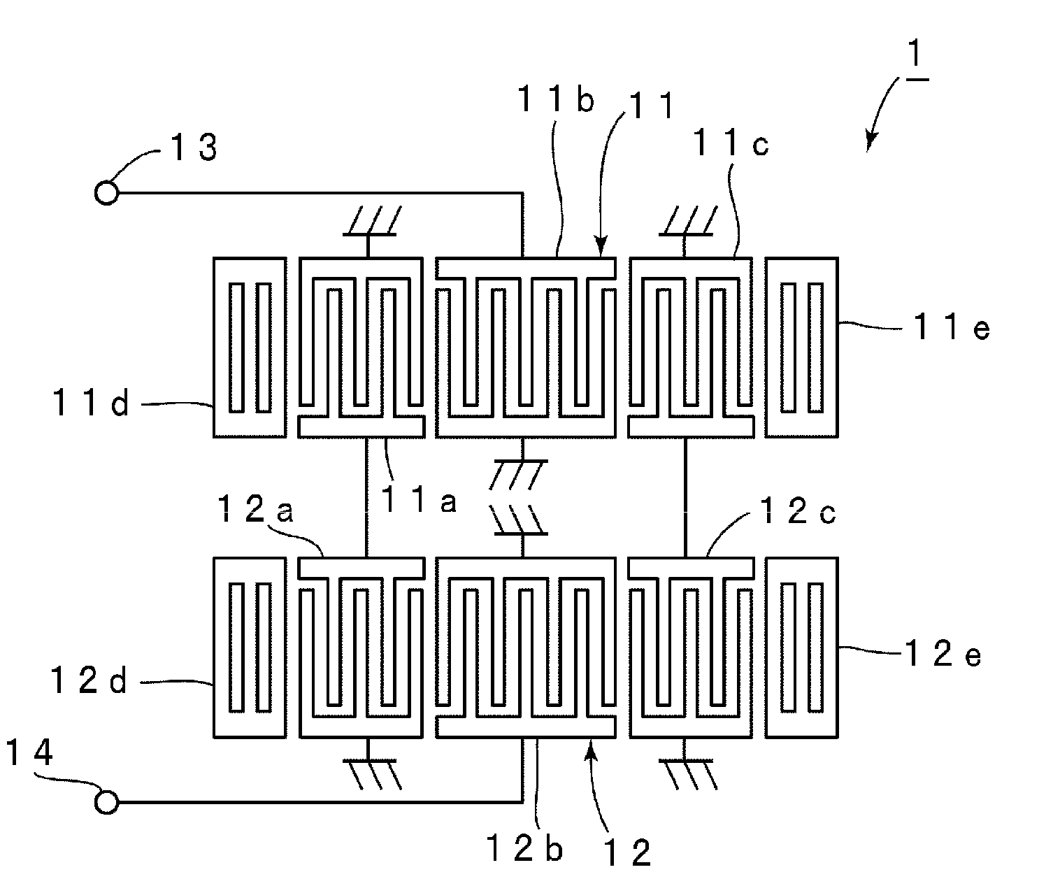
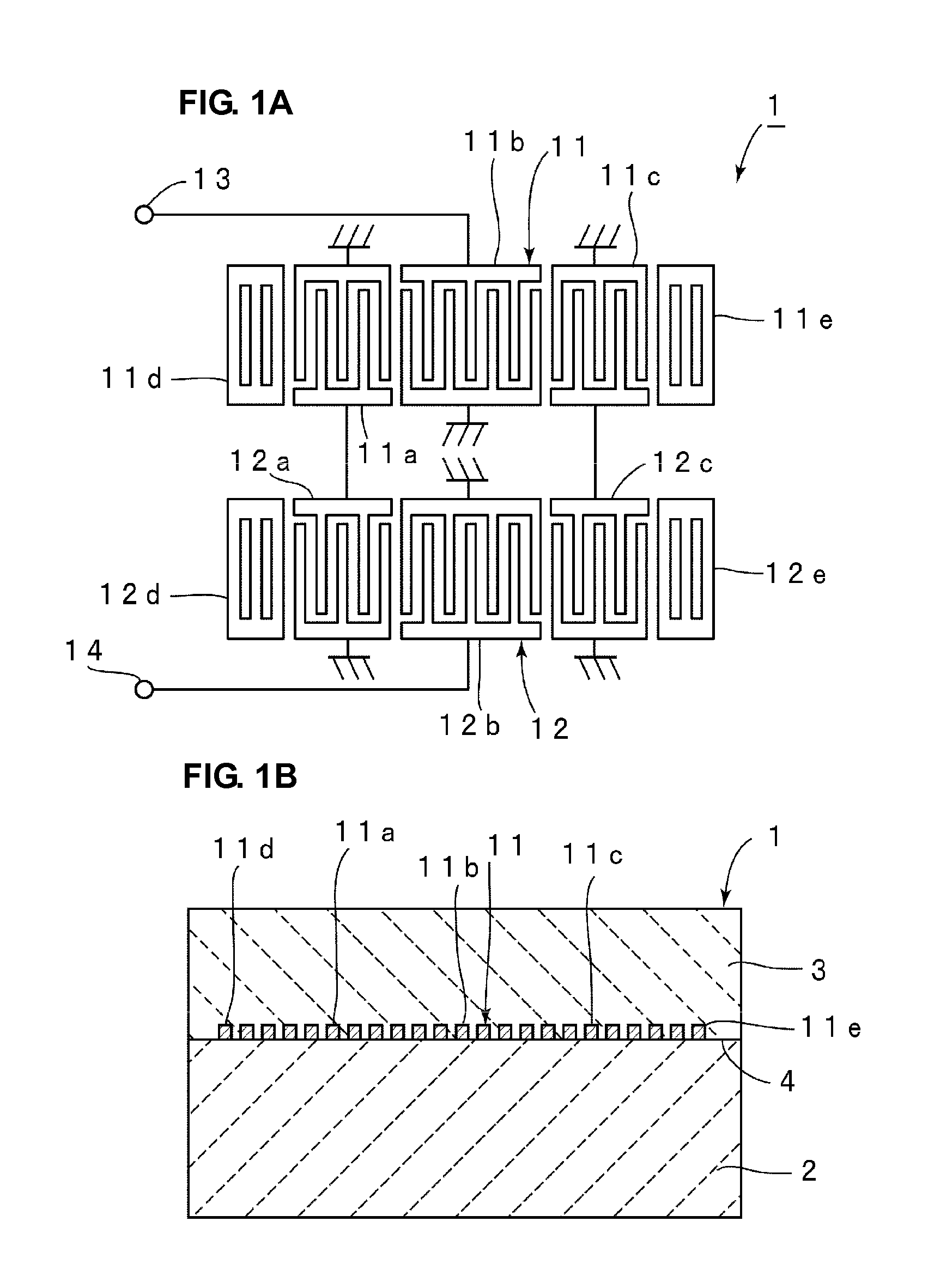
[0038]FIGS. 1A and 1B are a schematic front view showing an electrode structure used to describe a boundary acoustic wave filter according to a preferred embodiment of the present invention and a schematic front sectional view showing a structure of the boundary acoustic wave filter.

[0039]A boundary acoustic wave filter 1 includes a first medium 2 and a second medium 3. The first medium 2 is defined by a piezoelectric substance. The piezoelectric substance defining the first medium 2 is not particularly limited. However, in this preferred embodiment, the first medium 2 is preferably a 20° Y-cut, 20° X-direction propagation LiNbO3 substrate, for example.

[0040]On the other hand, the medium 3 is made of SiO2 in this preferred embodiment. However, the medium 3 may be made of any suitable dielectric.

[0041]On an interface bet...


PUM


Abstract

An elastic wave filter of a resonator type includes at least one IDT electrode arranged so as to contact the piezoelectric substance. The elastic wave filter is arranged such that an elastic wave in a main propagation mode for obtaining target frequency characteristics and an elastic wave in a sub-propagation mode propagate, the elastic wave being capable of propagating simultaneously with the elastic wave in the main propagation mode, an electromechanical coefficient K2 of the elastic wave in the sub-propagation mode is in the range from about 0.1% to about one third of an electromechanical coefficient K2 of the elastic wave in the main propagation mode, and a sound velocity of the elastic wave in the sub-propagation mode differs from a sound velocity of the elastic wave in the main propagation mode.

Description

BACKGROUND OF THE INVENTION[0001]1. Field of the Invention[0002]The present invention relates to a resonator-type elastic wave filter utilizing, for example, a boundary acoustic wave or a surface acoustic wave. More particularly, the present invention relates to an elastic wave filter utilizing an elastic wave in a mode for obtaining a desired passband and an elastic wave in a mode different from the mode for obtaining the desired passband.[0003]2. Description of the Related Art[0004]Various resonator-type surface acoustic wave filters have been disclosed in order to provide size reduction and loss reduction. For surface acoustic wave filters of this type, a significant attenuation amount near the passband and outside the passband is highly desired. In order to increase an attenuation amount outside the band, for example, in Japanese Unexamined Patent Application Publication No. 6-260876, a surface acoustic wave filter apparatus is disclosed in which a trap-type series resonator is ...

Claims


Application Information

Patent Timeline
IPC IPC(8): H03H9/64
CPCH01L41/047H03H9/0222H03H9/6469H03H9/6496
Inventor KANDO, HAJIME
Owner MURATA MFG CO LTD
Why Eureka
Try Eureka