Element substrate, printhead, head cartridge, and printing apparatus

a printing apparatus and printhead technology, applied in printing, other printing apparatus, etc., can solve the problems of inability to meet the voltage proof required of a switching element, leakage current sometimes occurring, and inability to print and print abnormally, so as to increase the chip size of the printhead, prevent abnormal printing and printhead damage

Inactive Publication Date: 2008-12-18
CANON KK
View PDF8 Cites 0 Cited by
  • Summary
  • Abstract
  • Description
  • Claims
  • Application Information

AI Technical Summary

Benefits of technology

[0034]The invention is particularly advantageous since it enables abnormal printing and printhead damage to be prevented with minor improvement to the drive power voltage generation portion of a switching element, without increasing the chip size of the printhead, even in the case where an abnormality occurs in the power supply that applies a voltage to a logic circuit.

Problems solved by technology

However, this configuration of inkjet is exemplary in nature and is not intended.
However, while a large current flows in order to drive the electrothermal transducer, leakage current sometimes occurred due to the pn reverse bias junction between the drain and the well not being able to withstand the high electric field when the conventional MIS field-effect transistors 130 are operated.
In such cases, the voltage proof required of a switching element could not be satisfied.
Therefore, this cannot be considered a realizable method.
Further, it is also known to apply the temperature sensor in cases such where a sequence is forcibly interrupted using a monitor value of the temperature sensor when an abnormality of some description occurs on the substrate, such as a power short circuit, causing the substrate temperature to be abnormally high.
In the case where a voltage is not applied to a logic circuit because the power supply that applies the voltage has failed for some reason, the logic of the logic circuit becomes unstable, creating the possibility of unnecessary voltages being applied to the electrothermal transducers or switching elements.
When this happens, the element substrate may also not function normally due to the logic of the element substrate getting out of control, resulting in abnormal printing or the like.

Method used


Image

  • Element substrate, printhead, head cartridge, and printing apparatus
  • Element substrate, printhead, head cartridge, and printing apparatus
  • Element substrate, printhead, head cartridge, and printing apparatus

Examples


first exemplary embodiment

[0072]FIG. 16 is a top view showing the arrangement of elements on an element substrate for an inkjet printhead according to a first exemplary embodiment of the present invention. An element substrate 101 has formed thereon switching elements 41, which are DMOS transistors, and electrothermal transducers 103 having the configurations shown in FIG. 7, and level shift circuits 49 which include a level shift element such as shown in FIG. 10. The element substrate 101 also has formed thereon a plurality of pads (terminals) 104, level shift circuit input voltage pads 105 utilized for receiving supply of input voltages for the level shift circuits 49 and drive signals for the switching elements 41 from an external source, and ink supply port forming portions 107.

[0073]The switching elements 41 and the electrothermal transducers 103 are provided in two rows over a 1200 dpi (dots per inch) interval with the ink supply port forming portions 107 sandwiched therebetween. Each row has at least ...

second exemplary embodiment

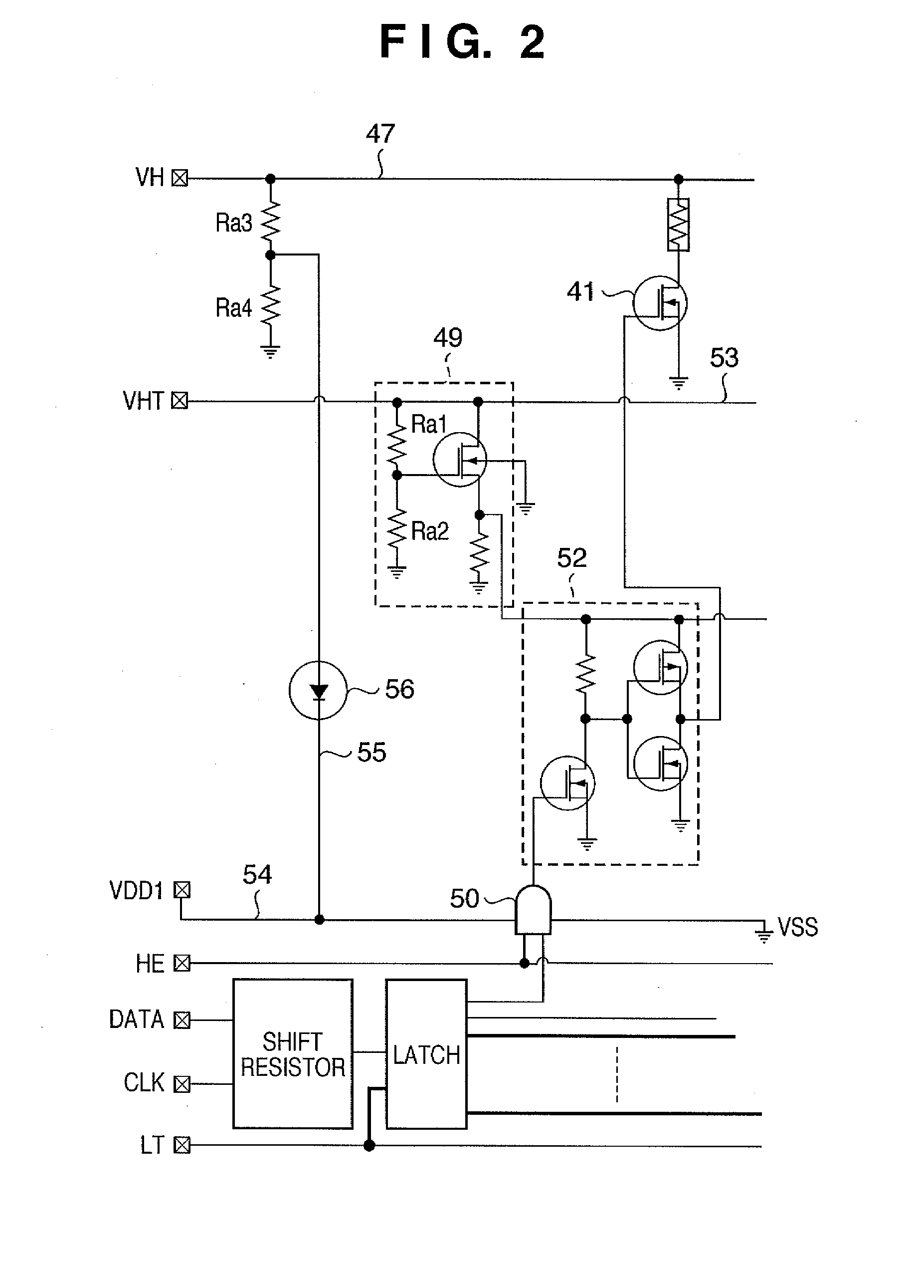
[0082]Next, an example circuit configuration of the second exemplary embodiment will be described in detail using FIG. 2. FIG. 2 shows a circuit configuration in the case where a second logic circuit voltage 55 that does not operate during normal operation is generated from a power supply voltage 47 (VH) which is the drive voltage of an electrothermal transducer and allows current to flow to the electrothermal transducer. In this configuration, the power supply voltage 47 is also stepped down between Ra3 and Ra4 using resistance ratio division in order to generate the second logic circuit voltage 55. For example, assume to the power supply voltage 47 is 24V. The VH terminal in FIG. 2 is a printing element drive voltage input terminal.

[0083]Given that the first logic circuit voltage 54 (e.g., 3.3V) operates during normal operation, the second logic circuit voltage 55 generated by resistance division is set to 3.3V or less relative to this voltage, so as to not contribute to the opera...

third exemplary embodiment

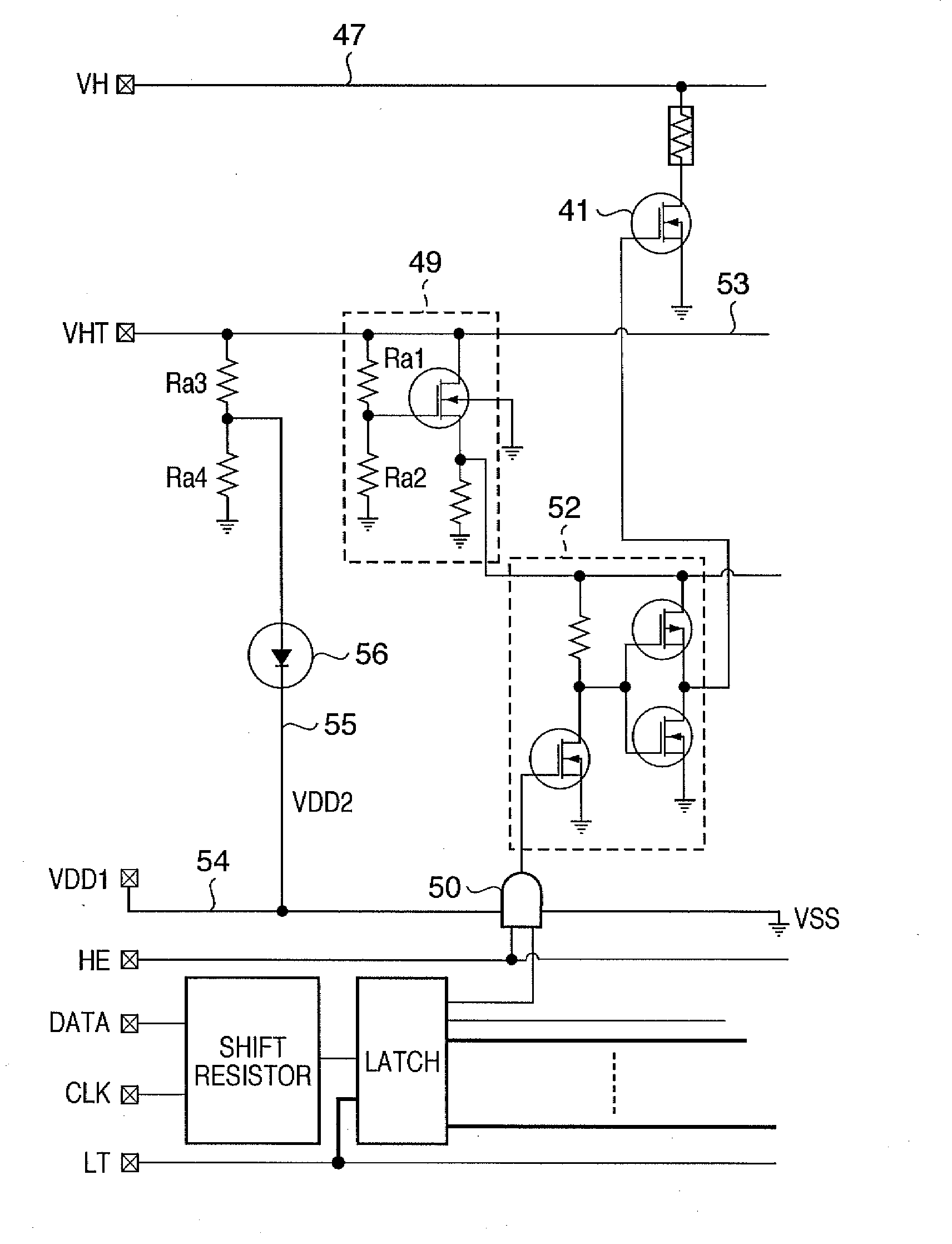
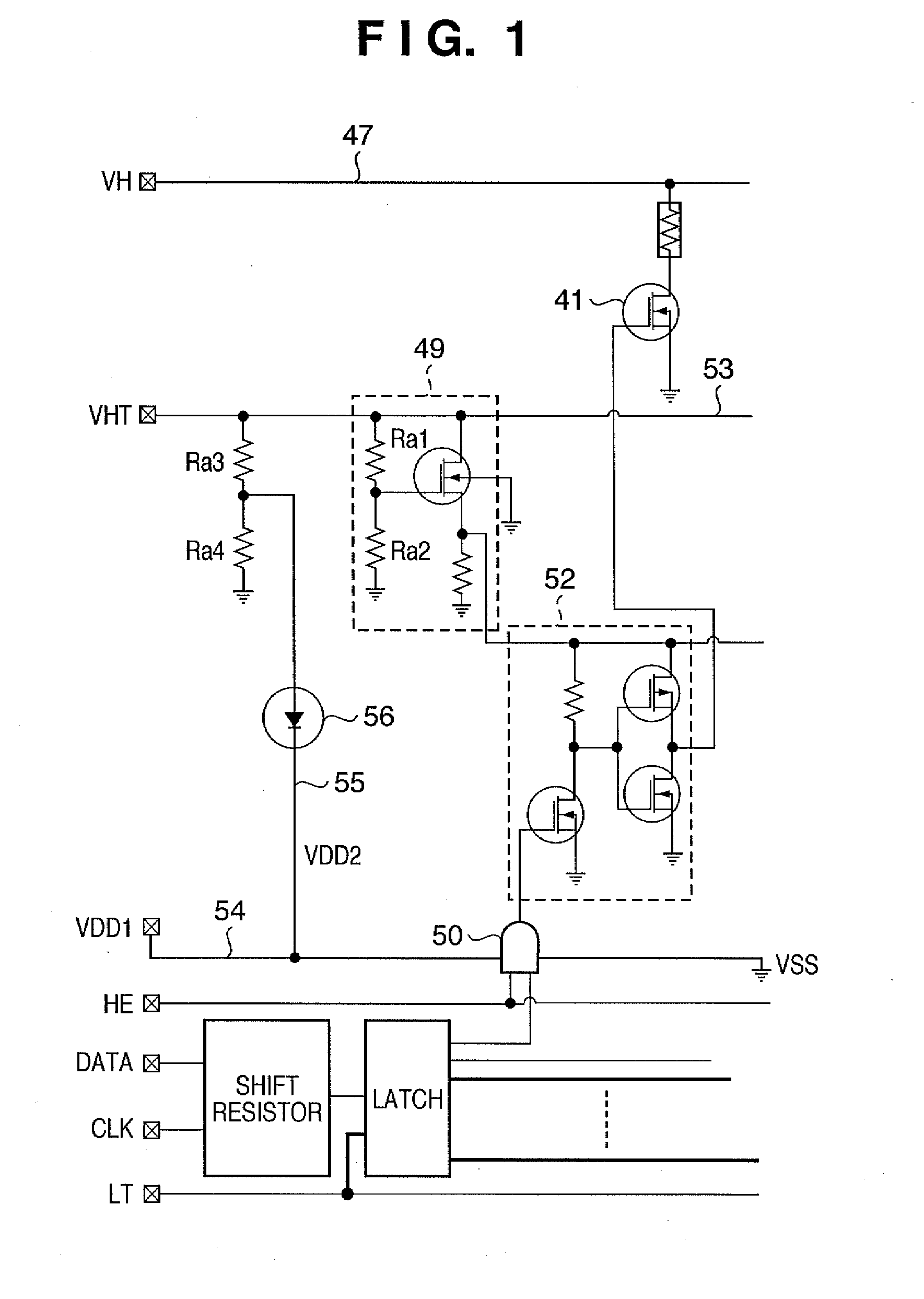
[0084]Next, an example circuit configuration of the third exemplary embodiment will be described in detail using FIG. 18. FIG. 18 shows a circuit configuration embodiment in the case where a second logic circuit voltage 55 that does not contribute to the operation of the logic circuit during normal operation is generated from a power supply voltage 47 for allowing current to flow to an electrothermal transducer, using part of the configuration of the level shift circuit 49. In FIG. 18, the VH terminal is a printing element drive voltage input terminal.

[0085]First, assume the input voltage from the level shift circuit input voltage pad is 24V, for example. The voltage is stepped down by resistance ratio division for use in the source follower, with the resistors set so that Ra1:Ra2=1:1 to give an input voltage (VHT) to the switching element 41 of 12V. Note that because the voltage is fixed, current consumption is considered to increase if an element with a low resistance value is uti...


PUM


Abstract

The present invention prevents an element substrate from not operating normally in the case where the voltage supply from a power supply that applies a voltage to a logic circuit is unstable. The element substrate of the invention has unit for applying a first voltage to the logic circuit, and unit capable of applying a second voltage that is lower than the first voltage and capable of operating the logic circuit.

Description

BACKGROUND OF THE INVENTION[0001]1. Field of the Invention[0002]The present invention relates to an element substrate that is used in an inkjet printhead or the like and has an electrothermal transducer that produces discharge energy, a switching element for driving the electrothermal transducer and a logic circuit that controls the switching element, and to a printhead having such an element substrate, a head cartridge and a printing apparatus.[0003]2. Description of the Related Art[0004]An inkjet printhead that utilizes thermal energy to discharge ink drops is able to realize a high density multi-nozzle configuration relatively easily, thereby enabling high resolution, high quality and high speed printing. One known method of discharging ink using this type of thermal energy is a side-shooter printhead that discharges ink drops vertically upwards of a surface on which an electrothermal transducer that produces thermal energy is formed. Generally, with this type of printhead, ink f...

Claims


Application Information

Patent Timeline
Patent Type & Authority Applications(United States)
IPC IPC(8): B41J29/38
CPCB41J2/1752B41J2/1753B41J2/17553
Inventor MATSUI, TAKAHIROIMANAKA, YOSHIYUKITAKEUCHI, SOUTAHATSUI, TAKUYAYAMAGUCHI, TAKAAKIKUBO, KOUSUKE
Owner CANON KK
Why Eureka
Try Eureka