Speaker driving device and audio output system

a driving device and speaker technology, applied in the direction of electrical transducers, transducer casings/cabinets/supports, gain control, etc., can solve the problems of excessive acoustic pressure of speakers, inability to adapt, and the size of ic chips must be increased, so as to achieve the effect of increasing the chip siz

Active Publication Date: 2006-05-04
GK BRIDGE 1
View PDF3 Cites 21 Cited by
  • Summary
  • Abstract
  • Description
  • Claims
  • Application Information

AI Technical Summary

Benefits of technology

[0018] The present invention solves the above conventional problem and an object of the present invention is to provide a speaker driving device and audio output system which, even when the speaker driving device is made to take the form of an IC chip constituting a semiconductor integrated circuit in a constitution where the dynamic speaker and piezoelectric speaker, which have different load impedances, can both be driven, make it possible to adapt to the respective driving of the dynamic speaker and piezoelectric speaker without increasing the chip size by suppressing the number of terminals and which make it possible to output a signal with the same power for the same input signal in the respective driving of the dynamic speaker and piezoelectric speaker.

Problems solved by technology

However, assuming a case where a dynamic speaker that is generally widely used to stabilize costs, for example, is used with this circuit constitution as is, a speaker with a lower load impedance than that of a piezoelectric speaker is driven, in the case of such speaker driving, the output power from the amplifier circuit 8 is large in comparison with a case where a piezoelectric speaker is driven, which results in the problem that the acoustic pressure from the speaker is excessive.
That is, the conventional speaker driving device and audio output system shown in FIG. 5 are unable to adapt without operational distinction to both driving types of the piezoelectric speaker and dynamic speaker with a different load impedance as driven speaker 1 by means of the same constitution and are unable to output a signal of the same power for the same input signal in the respective speaker driving.
When the speaker driving device is made into an IC chip as a semiconductor integrated circuit, the total number of terminals must be a number of terminals that takes into consideration control-terminal expansion such as a driving load switching terminal, which creates a new problem that the size of the IC chip must be increased.

Method used


Image

  • Speaker driving device and audio output system
  • Speaker driving device and audio output system
  • Speaker driving device and audio output system

Examples


first embodiment

[0034] The speaker driving device and audio output system of a first embodiment of the present invention will now be described.

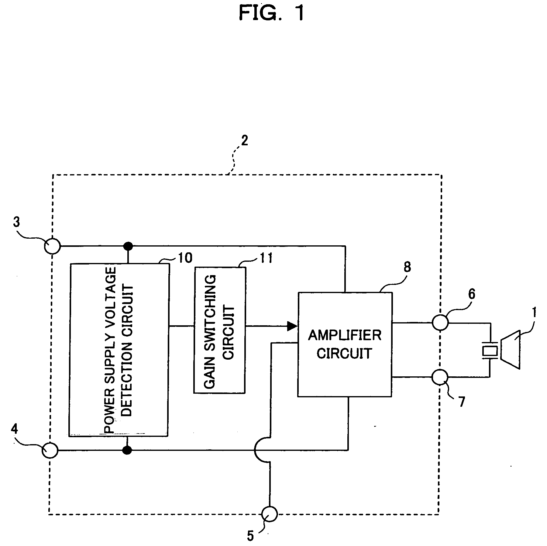
[0035]FIG. 1 is a block diagram showing a constitutional example of the speaker driving device and audio output system of the first embodiment of the present invention. In the speaker driving device 2 of the audio output system shown in FIG. 1, the amplifier circuit 8 is a circuit that amplifies a signal that is inputted from the input terminal 5 and drives a speaker 1 by means of output terminals 6 and 7, wherein a power supply voltage detection circuit 10, which detects the voltage of a power supply terminal 3 and determines whether the speaker connected to the output terminals 6 and 7 is a dynamic speaker or a piezoelectric speaker by means of the voltage, is connected between the power supply terminal 3 and ground terminal 4, and a gain switching circuit 11, which switches the voltage gain of the amplifier circuit 8 by means of the output of the power s...

second embodiment

[0042] The speaker driving device and audio output system of a second embodiment will now be described.

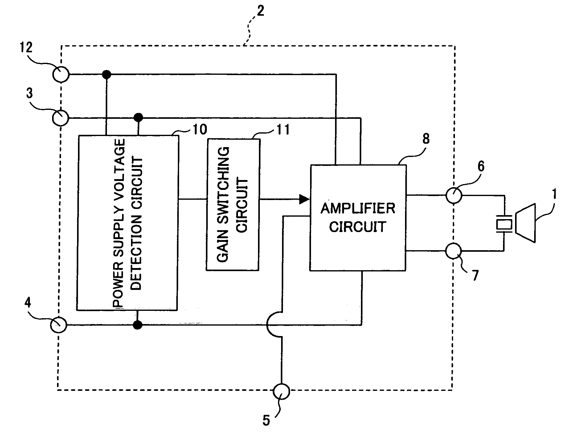
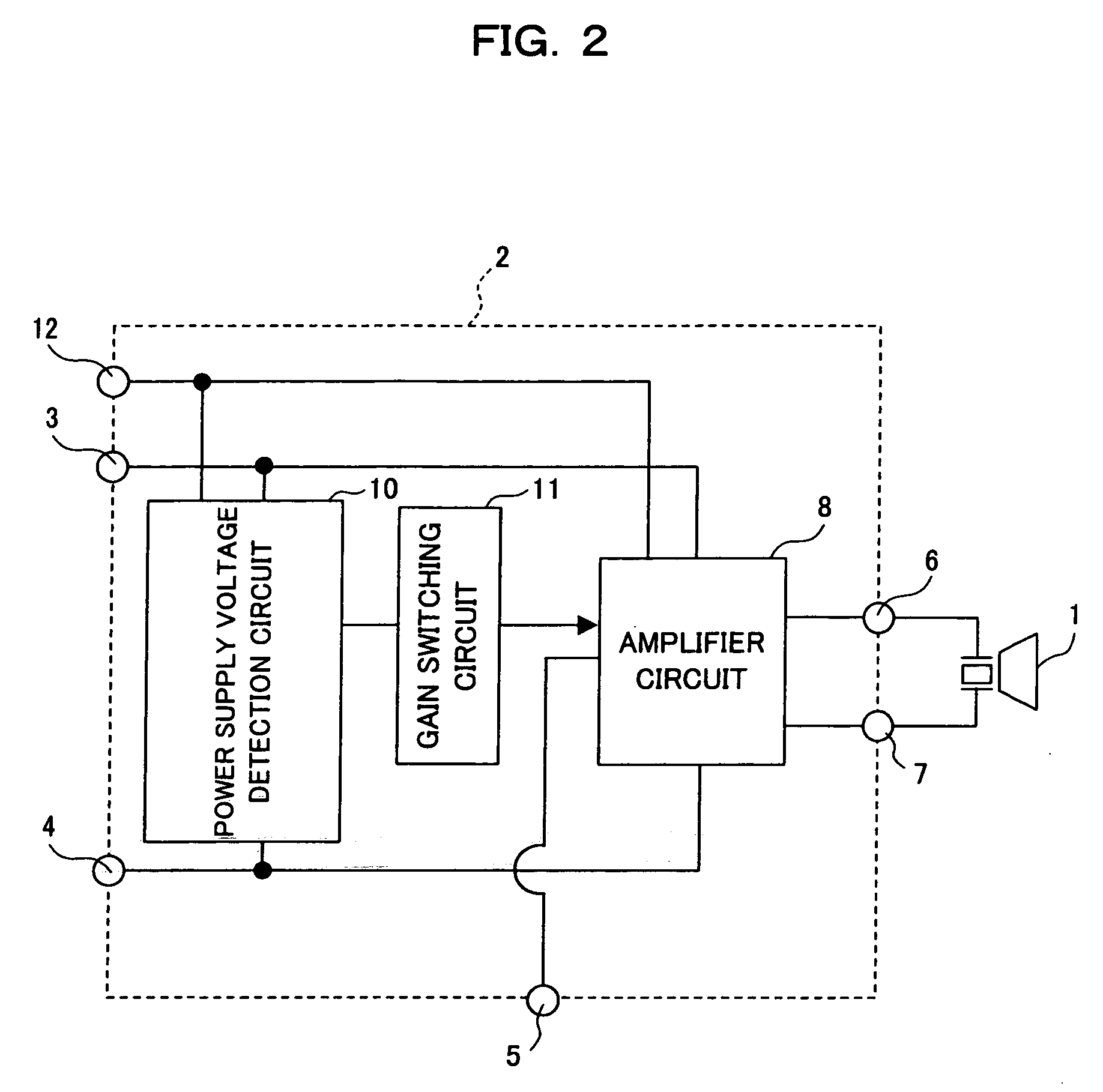
[0043]FIG. 2 is a block diagram showing a constitutional example of the speaker driving device and audio output system of the second embodiment of the present invention. In the speaker driving device 2 of the audio output system shown in FIG. 2, the amplifier circuit 8 is a circuit that amplifies a signal that is inputted from the input terminal 5 and drives a speaker 1 by means of output terminals 6 and 7, wherein the power supply terminal 3 is a power supply terminal for the output transistor of the amplifier circuit 8, and a driver power supply terminal 12 is a power supply terminal other than the output transistor in the amplifier circuit 8 and is a terminal for supplying a voltage that is higher than that of the power supply terminal 3, of approximately 7V, for example. The speaker driving device comprises the drive power supply terminal 12 in order to suppress the power cons...


PUM


Abstract

The present invention detects whether the supply voltage applied to the power supply terminal (3) is used for the dynamic speaker or for the piezoelectric speaker by the power supply voltage detection circuit (10), switches the gain of the amplifier circuit (8) in accordance with the detection result by the gain switching circuit (11) so that the same output power is produced for the same input signal in the respective speaker driving, and amplifies the input signal from the input terminal (5) by the amplifier circuit (8) having the gain to drive a speaker (1) that is connected to the output terminals (6, 7).

Description

BACKGROUND OF THE INVENTION [0001] 1. Field of the Invention [0002] The present invention relates to a speaker driving device and audio output system that drive a speaker mounted in a portable device such as a cellular phone, for example, by means of an output signal obtained by amplifying an input signal. [0003] 2. Description of the Related Art [0004] Conventionally, in the case of a device in which a speaker is mounted, i.e. a portable device such as a digital video camera (DVC), digital still camera (DSC), cellular phone, or notebook personal computer, for example, when a speaker driving device that drives the speaker takes the form of an IC and constitutes an audio output system together with the speaker, there is a multiplicity of cases where a piezoelectric speaker is used with the objective of a small footprint as the mounted speaker. [0005] A conventional speaker driving device for driving such a piezoelectric speaker and an audio output system will be described hereinbelow...

Claims


Application Information

Patent Timeline
Patent Type & Authority Applications(United States)
IPC IPC(8): H04R29/00H04R3/00
CPCH03F3/20H03G3/007H03G3/3026
Inventor YAMAMOTO, MAKOTOFUJII, KEIICHI
Owner GK BRIDGE 1
Why Eureka
Try Eureka