Voice coil type lens drive assembly

a voice coil and lens drive technology, applied in the direction of dynamo-electric components, dynamo-electric machines, instruments, etc., can solve the problems of poor efficiency of the lens drive assembly, difficult to apply the above construction to a downsized lens drive assembly, etc., to achieve convenient handling, improve the accuracy of winding height, and facilitate stabilization

Inactive Publication Date: 2008-10-23
CHUNG HUANG TIEN
View PDF3 Cites 59 Cited by
  • Summary
  • Abstract
  • Description
  • Claims
  • Application Information

AI Technical Summary

Benefits of technology

[0009]The voice coil type lens drive assembly described in claim 1 comprises a base, an electrically conductive spring disposed on the base, a metallic yoke disposed on the electrically conductive spring, magnets mounted within the yoke, a movable unit inserted into the yoke in opposition to the magnets, a leaf spring disposed on the yoke, and an upper cover frame coupled to the base while being superimposed on the leaf spring, the movable unit comprising a coil base and coils, the coil base comprising a cylindrical body centrally formed with a lens loading portion and having a qu...

Problems solved by technology

As a result, the gap between the coil 123d and the magnet M becomes wider and hence the magnetic repulsive force induced upon energization cannot be utilized effectively, thus affording a lens drive assembly of poor efficiency.
At the same time, an outli...

Method used


Image

  • Voice coil type lens drive assembly
  • Voice coil type lens drive assembly
  • Voice coil type lens drive assembly

Examples


Embodiment Construction

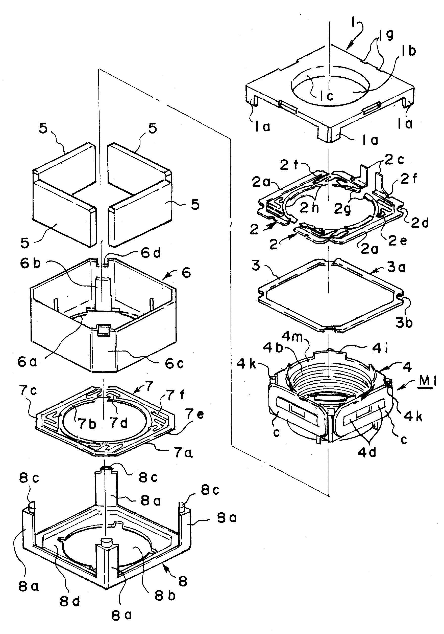
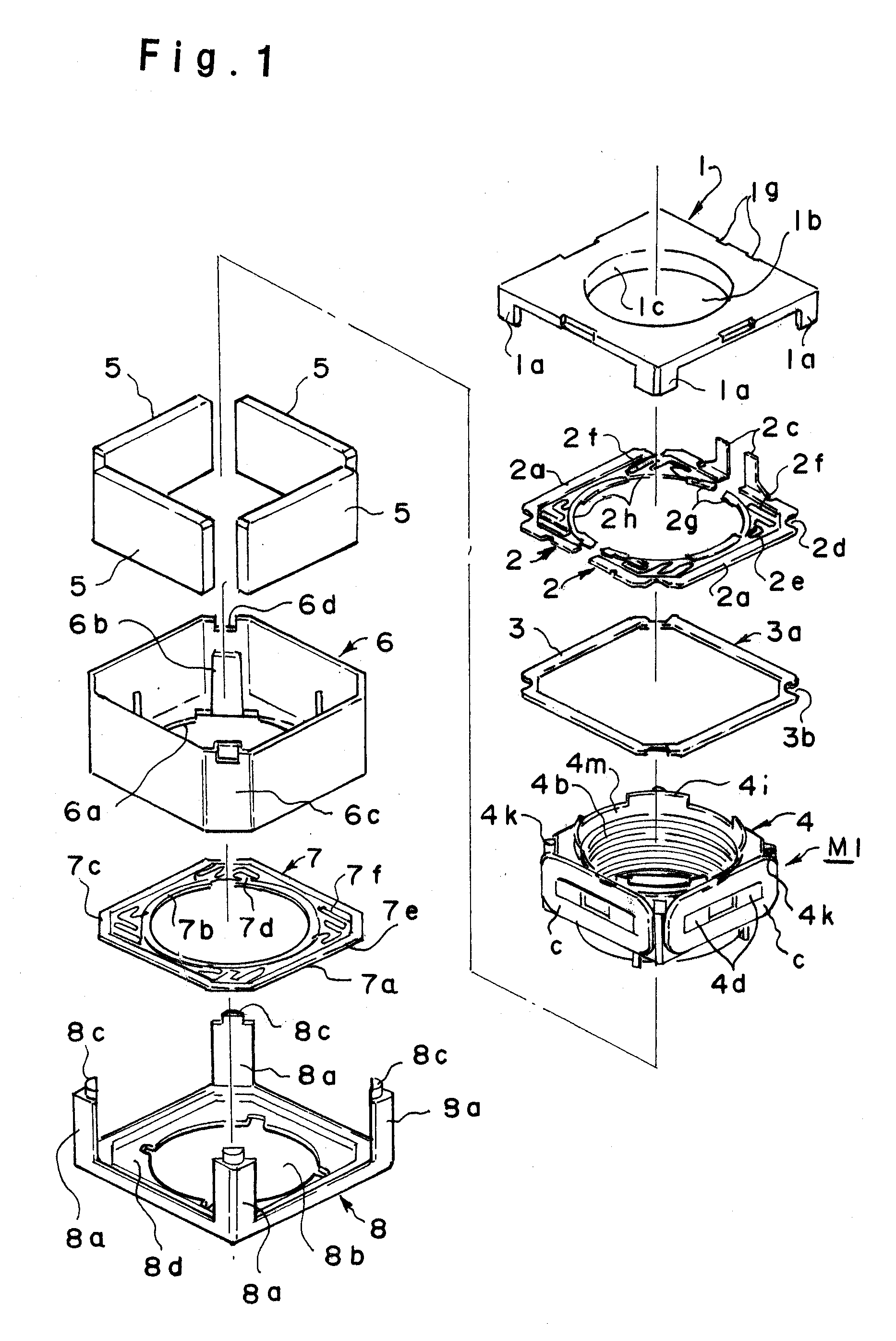
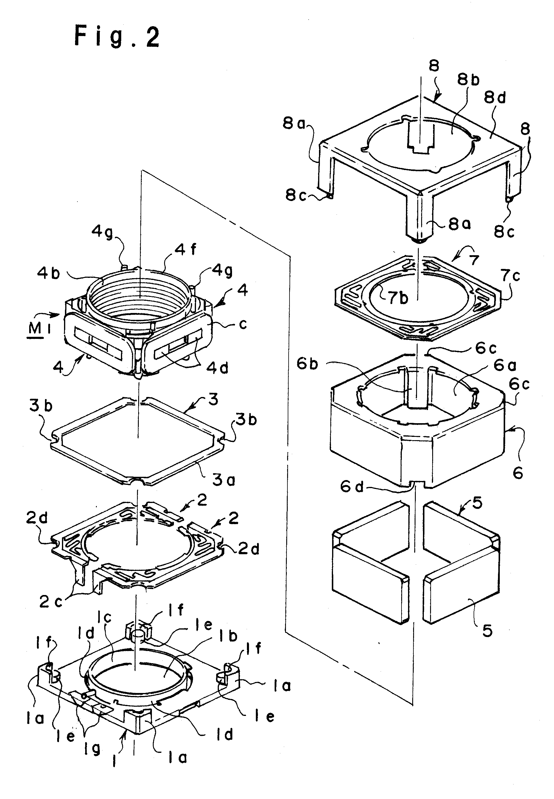
[0025]An embodiment of the present invention will now be described in detail with reference to the drawings. As shown in FIG. 1, a voice coil type lens drive assembly using a motor embodying the present invention is constituted by stacking within a cover frame 8 a leaf spring 7, a yoke 6, magnets 5, a coil base 4, a washer 3, electrically conductive springs 2 and a base 1 in this order. In the exploded perspective view for assembly of FIG. 1, as is seen from FIG. 2, the cover frame 8 to be positioned on an upper side is placed below and the components which should underlie the cover frame 8 are assembled successively upwards.

[0026]As shown in FIG. 2, the base 1 includes a body which is formed by molding in a quadrangular plate shape with use of a synthetic resin, and four support rods 1a projecting upwards are formed on the four corners of the body. A lens aperture 1b is formed centrally of the body and a cylindrical guide 1c is erected along a peripheral edge of the lens aperture.

[...


PUM


Abstract

By maintaining a relative position of coils of a movable unit with respect to fixed magnets in a normal state to stabilize a relative position of the movable unit with respect to the whole of a lens drive assembly, the lens drive assembly is provided as an assembly capable of adjusting the focus of a lens in a satisfactory manner.
In a voice coil type lens drive assembly for adjusting the focus of a lens, a spring 6, a yoke 6 with magnets 5 and a movable unit M1 attached thereto, and electrically conductive springs 2, are accommodated in this order on a base 1 and a connecting portion of a cover frame 8 and that of the base 1 are connected together to unite the two components. At the same time, cut-in portions 6d formed in end portions of the yoke 6 which is a metallic yoke are fitted on projections 1e of the base 1 and both are joined together with connections to the cover frame 8 as guide.

Description

BACKGROUND OF THE INVENTION[0001]1. Field of the Invention[0002]The present invention relates to a voice coil type lens drive assembly for adjusting the focus of a lens by utilizing a repulsive magnetic force which a magnetic field created upon energization of a coil induces between the coil and a fixed magnet opposed to the coil.[0003]2. Description of the Related Art[0004]Heretofore, in connection with a voice coil type lens drive assembly for adjusting the focus of a lens by utilizing a repulsive magnetic force which a magnetic field created upon energization of a coil induces between the coil and a fixed magnet opposed to the coil, a method for winding the coil around a movable unit has been known as is disclosed, for example, in Patent Literature 1 (Japanese Registered Utility Model No. 3127325, see FIG. 7). According to this conventional method, as shown in FIG. 15, a coil 123d having been wound beforehand in a predetermined shape is mounted suitably around a coil base 243.[00...

Claims


Application Information

Patent Timeline
IPC IPC(8): G02B7/04
CPCG02B7/08H02K33/18H02K41/0356
Inventor CHUNG, HUANG TIEN
Owner CHUNG HUANG TIEN
Why Eureka
Try Eureka