
Methods and apparatuses for user controlled beamforming

a beamforming and user-controlled technology, applied in direction finders, signals, instruments, etc., can solve the problems of reducing the reception of competing environmental sounds otherwise considered extraneous noise, increasing the receiver sensitivity, and reducing the sensitivity in the direction of interference, so as to facilitate user control of the direction

Inactive Publication Date: 2008-10-23
NOKIA CORP
View PDF7 Cites 120 Cited by
  • Summary
  • Abstract
  • Description
  • Claims
  • Application Information

AI Technical Summary

Benefits of technology

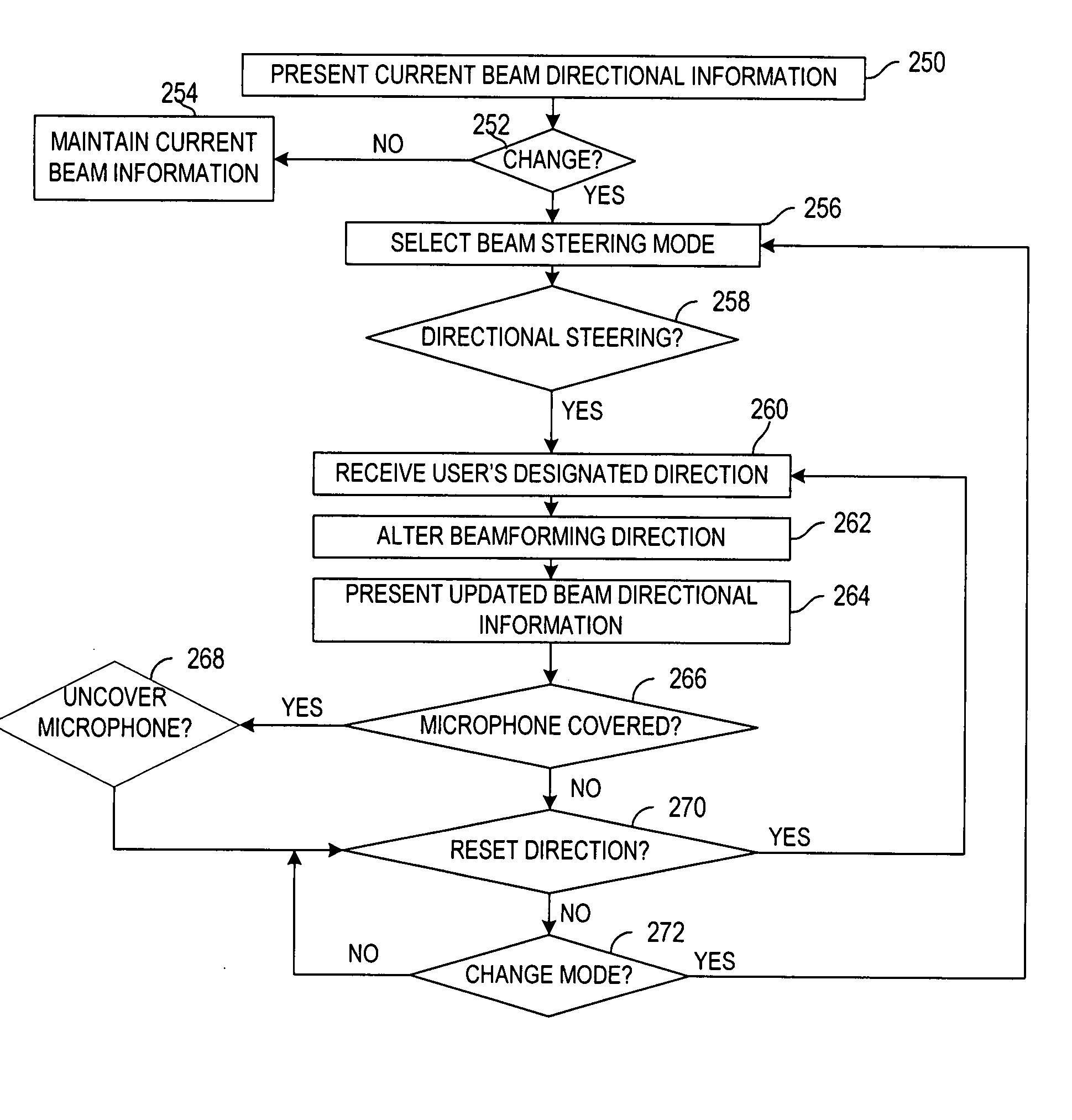
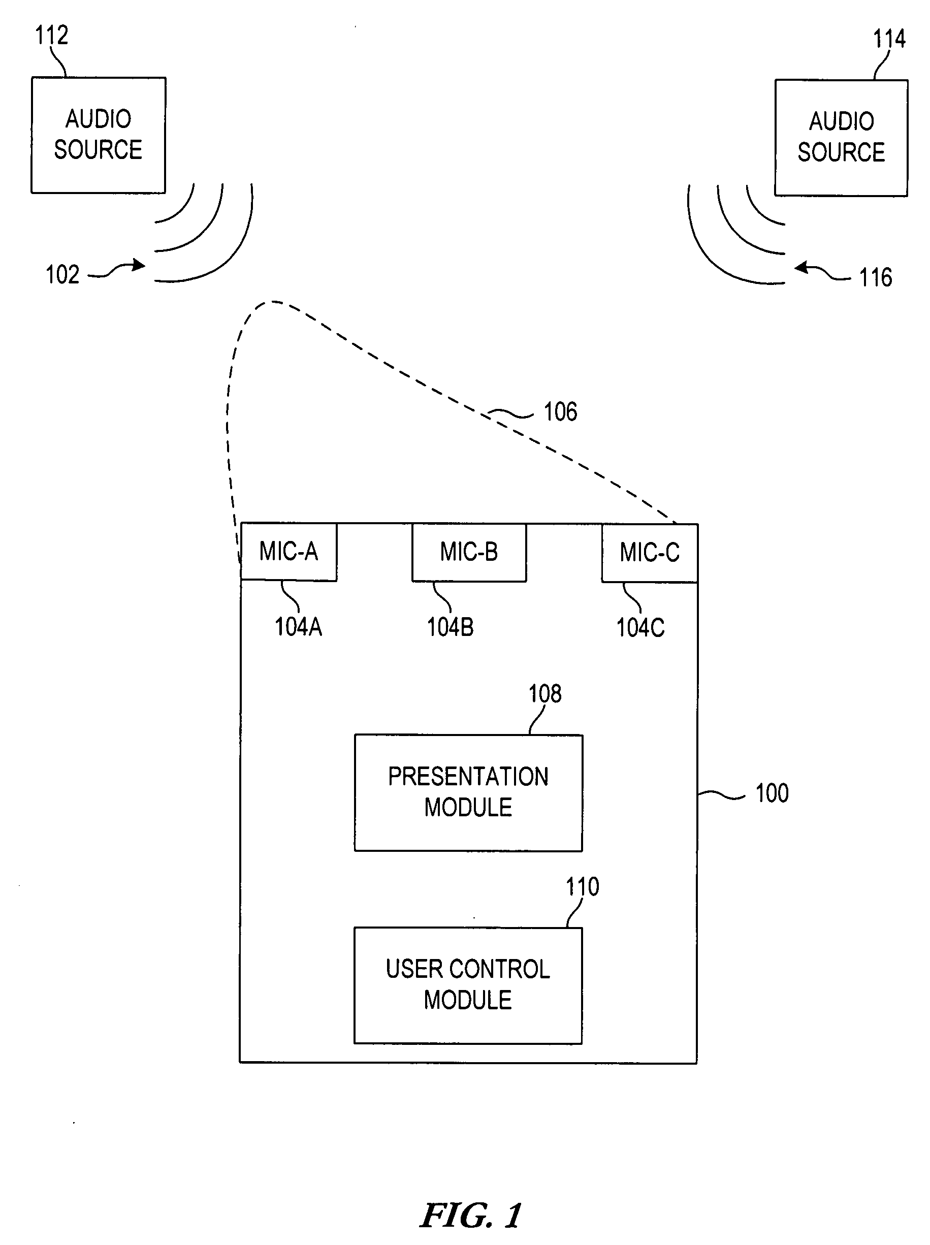
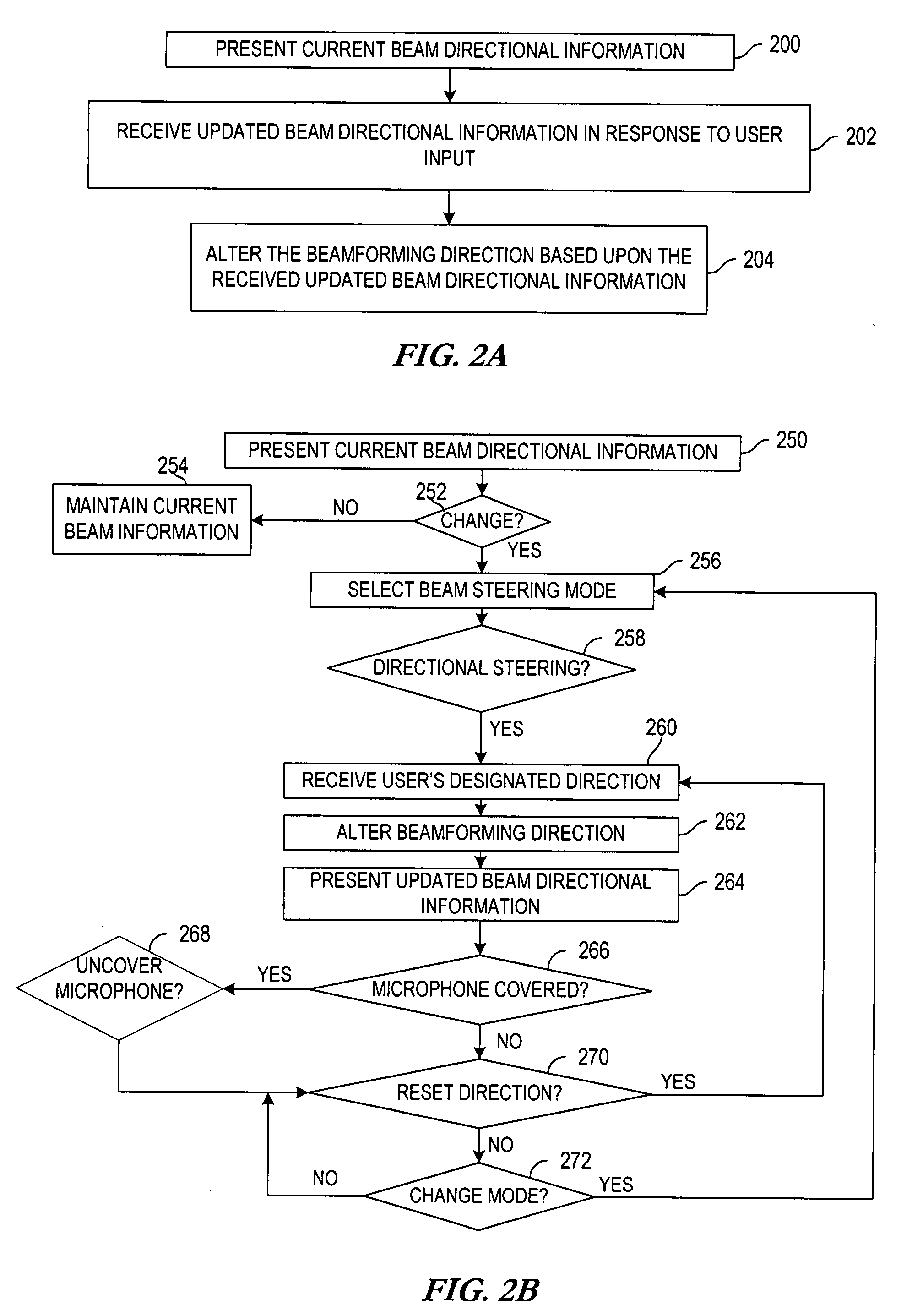
"The present invention provides methods and apparatuses for controlling beamforming in a transducer array. The technical effects include presenting current beam directional information via a user interface and receiving updated beam directional information in response to user input, altering beamforming direction based upon the received updated beam directional information, and providing a plurality of selectable modes for beam steering. The apparatuses can be represented by a mobile device, a personal digital assistant, a video camera, etc. The invention also includes computer-readable media with instructions for controlling beamforming. The system includes one or more audio sources and a user-controllable beamforming device."

Problems solved by technology

This reduces the reception of competing environmental sounds otherwise considered extraneous noise.
When receiving a signal, beamforming can increase the receiver sensitivity in the direction of wanted signals and decrease the sensitivity in the direction of interference and noise.
However, these automatic adjustments cannot account for situations where a user desires to hear or receive sounds that are not in the direction toward which the device has steered.

Method used


Image

  • Methods and apparatuses for user controlled beamforming
  • Methods and apparatuses for user controlled beamforming
  • Methods and apparatuses for user controlled beamforming

Examples


Embodiment Construction

[0023]In the following description of exemplary embodiments, reference is made to the accompanying drawings which form a part hereof, and in which is shown by way of illustration various manners in which the invention may be practiced. It is to be understood that other embodiments may be utilized, as structural and operational changes may be made without departing from the scope of the present invention.

[0024]Generally, the present invention is directed to apparatuses and methods for a user to control the beamforming of multiple microphones in a device. The device, such as a mobile telephone, optionally displays current beamforming information such as the direction and shape of the beam under the current configuration. The device's user may optionally input different beamforming information such as a new direction for the beam to be aimed. Both the current and input information may be presented to the user via a user interface connected to the device. In response to the user-inputte...


PUM


Abstract

A method for controlling beamforming in a device by a user of the device is provided. The method includes presenting current beam directional information via a user interface and receiving updated beam directional information in response to user input. The method also includes altering beamforming direction based upon the received updated beam directional information.

Description

FIELD OF THE INVENTION[0001]This invention relates in general to improving the quality of received signals, and more particularly to methods and apparatuses for controlling the beamforming of multiple-transducer configurations.BACKGROUND OF THE INVENTION[0002]In a world full of noise, most of which is unwanted sound, multiple-transducer (multiple-microphone) configurations are used to receive desired sound signals in a device. These configurations, when electronically directed or steered toward a sound's source, allow for focused reception of the desired sound. This reduces the reception of competing environmental sounds otherwise considered extraneous noise. The signal processing technique that effects this steering is beamforming.[0003]Beamforming is used to improve the quality of a received signal by processing the signals received by an array of multiple transducers. Transducer array signal processing can be utilized to enhance the performance of the receiving system capturing t...

Claims


Application Information

Patent Timeline
Patent Type & Authority Applications(United States)
IPC IPC(8): G10K11/34
CPCG10K11/34H04R3/005H04R2430/20H04R2430/25H04R2499/11
Inventor HAPPONEN, AKI P.
Owner NOKIA CORP
Learn More