Apparatus having areas of reduced attenuation for imaging support

a technology of attenuation and imaging support, applied in electrical apparatus, medical science, diagnostics, etc., can solve the problems of presenting certain potential harm and injury to both medical personnel and patients, skin burns, hair loss and sterility loss, etc., to reduce the amount of imaging energy needed, reduce the attenuation or loss of imaging signal, and improve procedures

Inactive Publication Date: 2008-10-23
FALBO MICHAEL G +1
View PDF0 Cites 8 Cited by
  • Summary
  • Abstract
  • Description
  • Claims
  • Application Information

AI Technical Summary

Benefits of technology

[0009]Therefore, it would be a great benefit if a patient support surface could be developed which would reduce the imaging signal attenuation or loss of transmission of energy from an imaging beam emanating from an imaging source. Such a patient support surface would provide the benefits of reducing the amount of imaging energy necessary to allow the medical personnel to view the operating field during image-guided procedures. An imaging support surface having a lower degree of imaging beam attenuation could improve procedures in two ways: (1) this approach could improve image resolution at current energy levels thereby potentially hastening the procedure and / or improving the outcome; or (2) this approach could allow the use of lower amounts of imaging energy during image-guided procedures and would permit longer periods of time for medical procedures that are image-guided. In addition, a patient support surface which reduces the attenuation of the energy in an imaging beam would provide additional safety for both patient and medical personnel by reducing the total amount of exposure of both patients and medical personnel to radiation energy. For example, burns to patients.
[0010]One aspect of the prior art should be noted, for while it presents an opening in the surface of a patient imaging support surface it would not be useful for the problem addressed by the present embodiments. Referring to FIG. 2, an opening 44 is shown in the area of the support surface on which rests the head of a patient. When a patient is placed face down on the support surface, this opening receives the patient's nose and face and improves patient comfort during procedures performed in the prone position. Typically, this opening can have dimensions of five inches width and six inches length. While the face opening has been offered for several years in patient support tables, the purpose is patient comfort, and thus, it incorporates several limitations which eliminate its utility as a viewing field having an area of low attenuation. Further, these limitations obscure any suggestion that such a face opening would be useful in providing an area of reduced attenuation for use with an imaging signal.

Problems solved by technology

The use of such imaging energy, in particular, X-rays in fluoroscopy, present certain potentials for harm and injury to both medical personnel and patients.
High doses of radiation can result in skin burns, loss of hair and sterility.
A dose of about 600 rad can cause abnormal redness of the skin, whereas the radiation dose of 2000 rad can cause serious skin burns.
Since the highest dose delivered to a patient generally occurs on the skin at the point where the X-ray beam enters the patient, skin burns are the most frequent problem associated with current image-guided procedures.
One aspect of the prior art should be noted, for while it presents an opening in the surface of a patient imaging support surface it would not be useful for the problem addressed by the present embodiments.
While the face opening has been offered for several years in patient support tables, the purpose is patient comfort, and thus, it incorporates several limitations which eliminate its utility as a viewing field having an area of low attenuation.
Further, these limitations obscure any suggestion that such a face opening would be useful in providing an area of reduced attenuation for use with an imaging signal.
The size of the face opening is so small that an unobstructed field of view during an image-guided medical procedure could not be obtained because the opening is smaller than the receiver.

Method used


Image

  • Apparatus having areas of reduced attenuation for imaging support
  • Apparatus having areas of reduced attenuation for imaging support
  • Apparatus having areas of reduced attenuation for imaging support

Examples


Embodiment Construction

[0039]As required, detailed embodiments are disclosed herein; however, it is to be understood that the disclosed embodiments are merely exemplary of the invention, which may be embodied in various forms. Therefore, specific structural and functional details disclosed herein are not to be interpreted as limiting, but merely as a basis for the claims and as a representative basis for teaching one skilled in the art to variously employ the teachings in virtually any appropriately detailed structure.

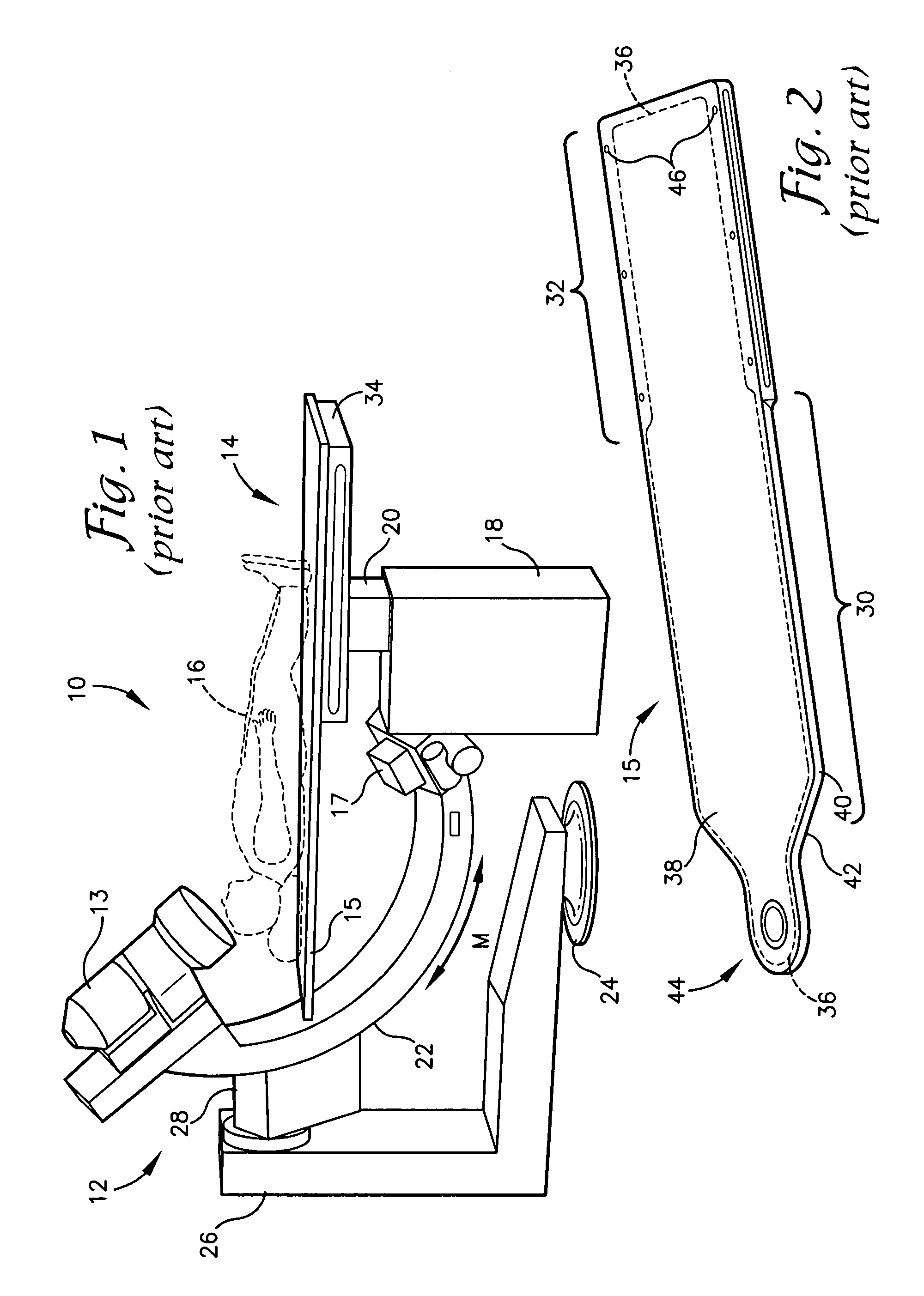
[0040]Referring now to FIG. 1, a typical medical imaging apparatus and patient support table combination 10 are shown. The combination of FIG. 1 is comprised of imaging device 12 and imaging patient support surface or imaging table 14. In general, these two devices are used together to provide a continuous or intermittent image of the positioning of surgical devices within a patient 16 during the course of an image guided diagnostic medical or surgical procedure. More particularly, a patient...


PUM


Abstract

A patient imaging support is provided having first and second areas of reduced imaging energy attenuation to avoid increased in imaging energy by automatic exposure control voids during use of a C-arm imaging device in the right anterior oblique (RAO) and/or left anterior oblique (LAO) positions and to allow reduction of the amount of X-ray energy or other imaging energy needed to produce an image of the procedure field and for observation by medical personnel.

Description

[0001]This application is a continuation-in-part of application Ser. No. 10 / 930,185 filed Aug. 31, 2004, titled Imaging Table Support Surface which is a continuation-in-part of application Ser. No. 10 / 346,218 filed Jan. 17, 2003 titled Imaging Table.FIELD OF THE INVENTION[0002]A patient imaging support surface embodiment is provided having plural areas of reduced imaging energy attenuation which assist in avoiding undesired increases in imaging energy due to the automatic exposure control (AEC) responding to the differential energy absorption between an area of reduced imaging energy attenuation and the imaging support. In one embodiment, the support surface is provided with an area of reduced support surface thickness or a void in the surface which is adjacent the portion of the patient's body that is the intended area of imaging or image-guided surgery. The area of reduced support surface thickness or a void decreases the attenuation of the imaging energy or X-ray energy that is n...

Claims


Application Information

Patent Timeline
Patent Type & Authority Applications(United States)
IPC IPC(8): H05G1/00
CPCA61B6/0442A61B6/4423
Inventor FALBO, MICHAEL G.SMOLER, MARTIN
Owner FALBO MICHAEL G
Why Eureka
Try Eureka