Plug-socket connector apparatus for optical fiber termination

a technology of plug-socket connectors and connectors, which is applied in the direction of optics, optical elements, instruments, etc., can solve the problems of inability to use optical communication with external devices, inability to place print circuit boards side by side in a horizontal direction, and large thickness dimension of electronic products equipped with plug-socket connectors, so as to improve the working efficiency of connection

Inactive Publication Date: 2008-10-23
MATSUSHITA ELECTRIC WORKS LTD
View PDF1 Cites 12 Cited by
  • Summary
  • Abstract
  • Description
  • Claims
  • Application Information

AI Technical Summary

Benefits of technology

[0022]In an embodiment of the second invention, the side faces of the first and second plug-bases are provided with first and second ribs for indicating rotation angles, respectively. The plug holder has first and second ma

Problems solved by technology

However, the apparatus is configured to be located between two printed circuit boards, and accordingly cannot be used for optical communication with external devices.
In addition, print circuit boards cannot be placed side by side in a horizontal direction.
However, since the hybrid plug is connected to the hybrid socket in a vertical posture with respect to the print circuit

Method used


Image

  • Plug-socket connector apparatus for optical fiber termination
  • Plug-socket connector apparatus for optical fiber termination
  • Plug-socket connector apparatus for optical fiber termination

Examples


Embodiment Construction

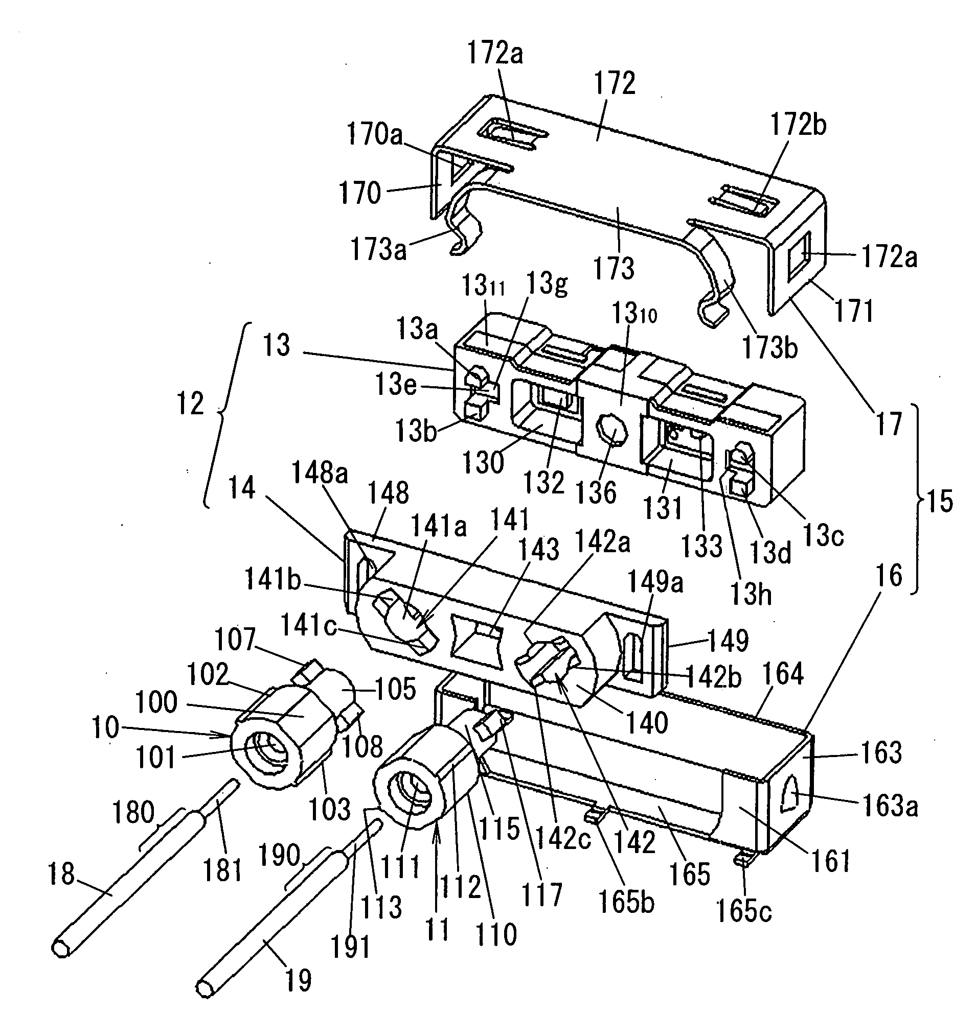
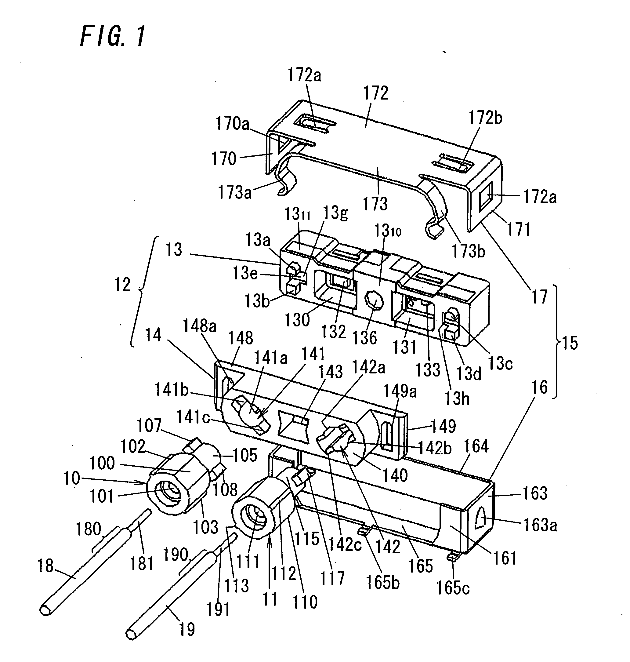
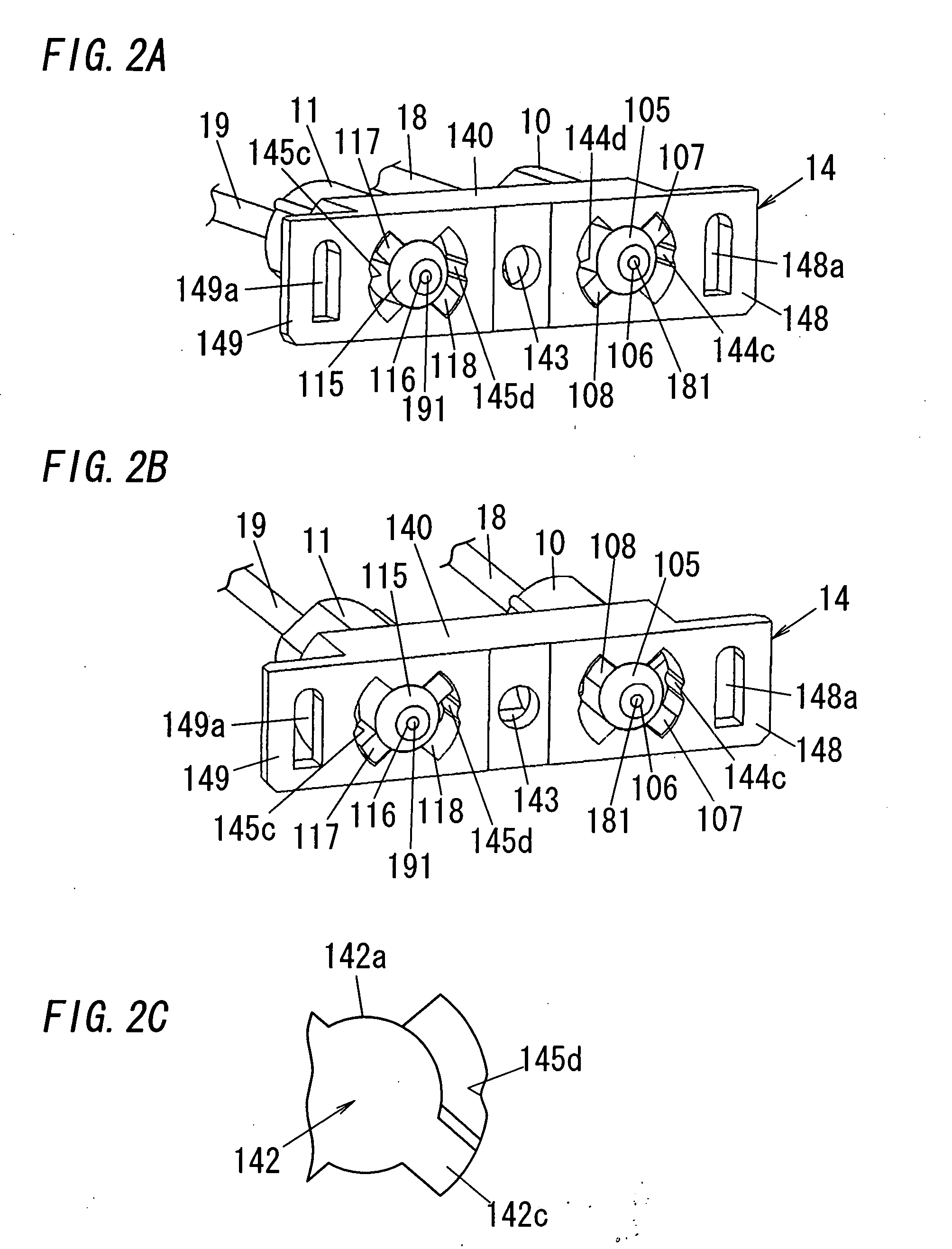
[0046]FIG. 1 shows plug-socket connector apparatus for optical fiber termination, in accordance with an embodiment of the present invention. This apparatus comprises first and second plugs 10 and 11, a socket 12, and a metal shell 15.

[0047]The first and second plugs 10 and 11 are fixed at one ends 180 and 190 of first and second optical fiber cables 18 and 19 enclosing first and second optical fibers 181 and 191, respectively. The plugs 10 and 11 are both single ferrule plugs and comprise first and second plug-bases 100 and 110 and first and second circular plug-tips 105 and 115, respectively. Each of the plugs 10 and 11 is also made of conductive material (e.g., conductive synthetic resin).

[0048]The first and second plug-bases 100 and 110 have first and second holes 101 and 111 into which the ends 180 and 190 of the cables 18 and 19 are inserted, respectively, and fixes the ends 180 and 190 inserted into the holes 101 and 111, respectively. For example, the ends 180 and 190 are res...


PUM


Abstract

Plug-socket connector apparatus for optical fiber termination comprises first and second plugs and a socket. The first and second plugs are both single ferrule plugs. The socket is a molded interconnect device and a plug holder, and includes terminals located on the bottom face of the socket, first and second bores located at one side of the socket, and first and second retainers. The retainers retain latches formed in the plugs so as to prevent the plugs from falling out of the bores and to restrict rotation angles of the plugs around the axes within predetermined rotation angle ranges, when the plugs is plugged in the bores.

Description

TECHNICAL FIELD[0001]The invention relates generally to an optical fiber connector and more particularly to plug-socket connector apparatus for optical fiber termination.BACKGROUND ART[0002]Japanese Patent Application Publication Number H11-329637 issued Nov. 30, 1999 discloses connection apparatus between printed circuit boards, which is formed of a transmission connector and a reception connector. The transmission connector is a molded interconnect device (MID) including a light emitting element, and is mounted on a first printed circuit board. The reception connector is an MID that includes a light receiving element facing the light emitting element, and is mounted on a second printed circuit board piled on the first printed circuit board. Since this apparatus transmits an optical signal through the light emitting element and light receiving element, contacts to be connected each other can be omitted. However, the apparatus is configured to be located between two printed circuit ...

Claims


Application Information

Patent Timeline
IPC IPC(8): G02B6/36
CPCG02B6/389G02B6/4292H01R11/01
Inventor SAKAJI, TAKAKOABE, YUTAKAHASHIMOTO, SHUNSUKE
Owner MATSUSHITA ELECTRIC WORKS LTD
Why Eureka
Try Eureka