
Multistage Planetary Gear

a planetary gear and multi-stage technology, applied in the direction of differential gearings, friction gearings, toothed gearings, etc., can solve the problem of occupying a large space for gear, achieve high moment transfer through elements, ensure reliable and controllable clutch functions, and achieve precise and reliable movement transfer.

Inactive Publication Date: 2008-10-23
ROTREX
View PDF9 Cites 4 Cited by
  • Summary
  • Abstract
  • Description
  • Claims
  • Application Information

AI Technical Summary

Benefits of technology

[0006]The object of the invention is to improve known multistage gears with the objective of making the gears compact, operationally reliable and suitable for extremely high speeds and transfer of high moments.
[0008]A compact two-stage gear may be constructed in this simple manner, where the transfer of the moment is utilized in the traction between the outer ring and the planet wheels, as described in WO 02 / 064997, when the clutch is not activated. Upon activation, the movement will be transferred via the gear transmission, which will result in a high gearing corresponding to the configuration of the gear wheel engagement.
[0010]When, as stated in claim 3, the planet shaft is used for the gear wheel engagement, a precise and reliable transfer of movement is achieved.
[0013]When, as stated in claim 6, the elements are provided with a tractive force toward the axis of rotation of the gear, a reliable and controllable clutch function is ensured.
[0014]When, as stated in claim 7, the gear is provided with two sets of planetary gears and the secondary gear may be engaged and disengaged, an increased gear ratio and speed of the output shaft may be achieved.
[0016]When, as stated in claim 9, the gear is constructed with one or more sets of gear stages, variable speeds of the driven mechanical gear may be achieved in a simple manner.

Problems solved by technology

This, however, is a relatively complicated gear to manufacture, and since many elements are incorporated in the gear, it is also subject to great wear which may cause break-down, just as the efficiency is reduced correspondingly.
Finally, the gear takes up much space because of its structure.

Method used


Image

  • Multistage Planetary Gear
  • Multistage Planetary Gear
  • Multistage Planetary Gear

Examples


Embodiment Construction

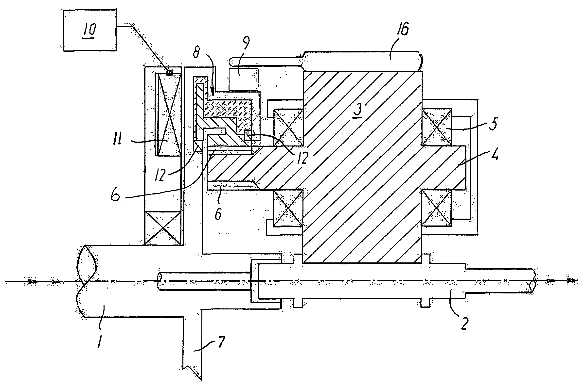
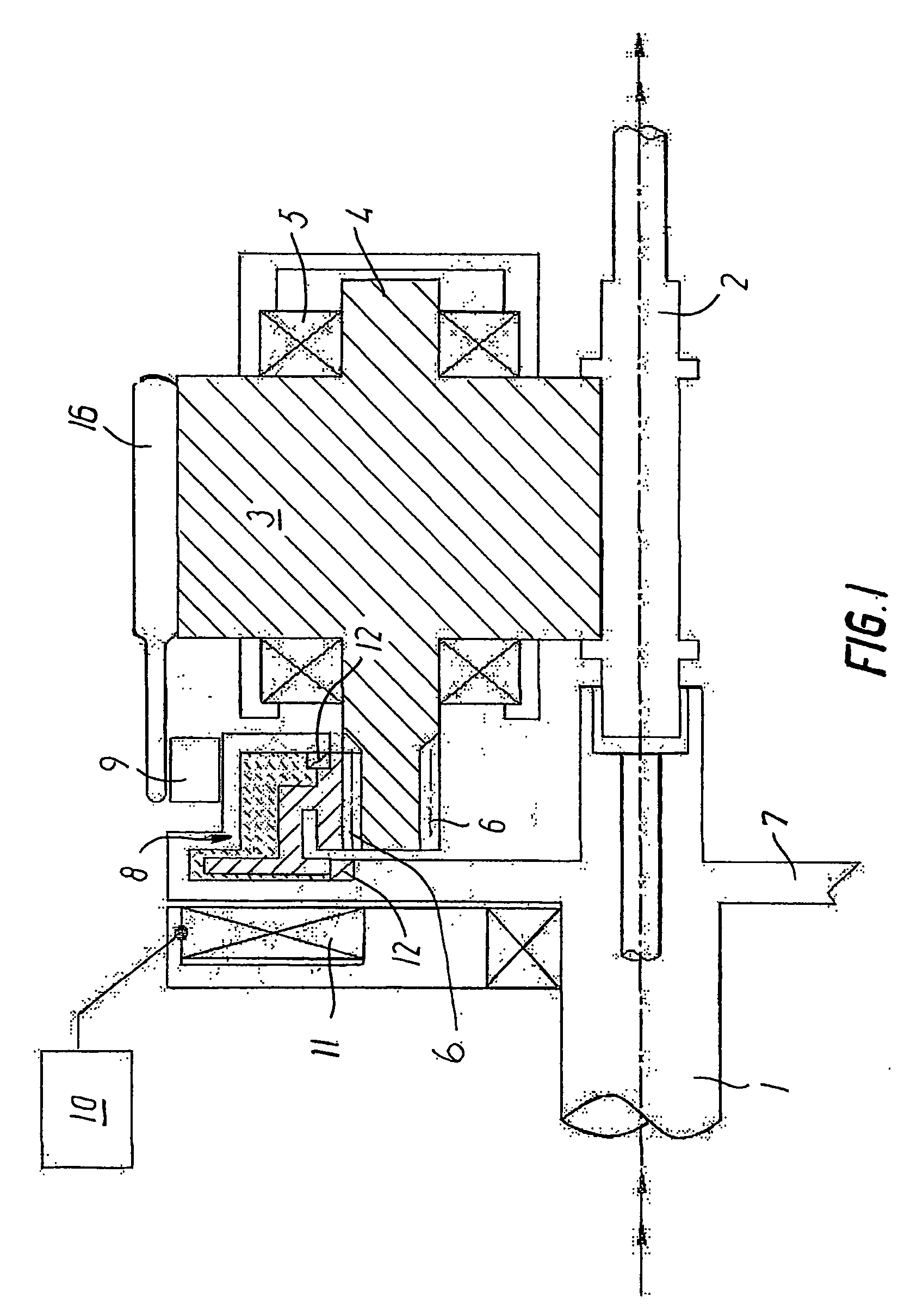
[0024]The first exemplary embodiment is indicated in FIG. 1 and shows a planetary gear which is expanded with a ring gear 6 on the stub shafts 4 of the planet wheels 3.

[0025]This provides a compact and relatively simple gear at low production costs and with great operational reliability.

[0026]As indicated in FIG. 1, the gear comprises a drive shaft, the input shaft 1, which is connected with a drive plate 7.

[0027]The clutch 8 comprises a toothed rim 6 on its one clutch part with internal toothing which rotates with the clutch. The clutch is constructed as an electromagnetic clutch which is isolated from the oil in the gear housing by means of gaskets 12.

[0028]A coil 11 is mounted on the gear housing, which coil 11 may be activated and controlled by means of a module 10 which allows remote control of the gear.

[0029]The movable part of the clutch comprises a magnetic core which will interconnect the parts when the coil 11 is energized.

[0030]The planetary gear has an outer ring 16 whic...


PUM


Abstract

When, according to the invention, a multistage planetary gear is constructed with a clutch / brake device (8, 21, 22) and these devices are constructed as remote-controlled or automatically operating clutches / brakes, it is possible to construct multistage gears which are compact, and which are reliable in operation. The gear stages are configured as cooperating tooth engagements (6, 6.1, 6.2) on rotating parts, which ensures the function at high speeds of rotation and allows transfers of great power.

Description

STATE OF THE ART[0001]The invention relates to a multistage planetary gear incorporated in a gear housing and comprising an outer ring, planet wheels and a sun shaft.[0002]Planetary gears of this type are used in particular where high speeds and transfers of great power are needed. Compressors for internal combustion engines may be mentioned as an example.[0003]An example of a two-stage gear of the planetary gear type is known from U.S. Pat. No. 6,609,505, which gear is useful for the driving of a centrifugal charger for an internal combustion engine.[0004]This gear is composed of two entire planetary gears which are interconnected such that selected parts of the gear may be braked. This, however, is a relatively complicated gear to manufacture, and since many elements are incorporated in the gear, it is also subject to great wear which may cause break-down, just as the efficiency is reduced correspondingly. Finally, the gear takes up much space because of its structure.[0005]A plan...

Claims


Application Information

Patent Timeline
Patent Type & Authority Applications(United States)
IPC IPC(8): F16H3/44F16H15/56F16H3/04F16H3/66F16H3/72F16H13/04
CPCF16H3/04F16H3/66F16H3/663F16H3/721F16H13/04F16H2200/0034F16H2200/0039F16H2200/2005F16H2200/2007F16H2200/2023
Inventor KOLSTRUP, ANDERS PETER
Owner ROTREX
Learn More