
Method and apparatus for determining a combustion parameter for an internal combustion engine

a combustion parameter and internal combustion engine technology, applied in the direction of engine testing, structural/machine measurement, electrical control, etc., can solve the problems of insufficient energy in the rebreathed exhaust to produce reliable auto-ignition, method, and inability to work satisfactorily at or near idle speed and load conditions,

Inactive Publication Date: 2008-10-30
GM GLOBAL TECH OPERATIONS LLC
View PDF25 Cites 30 Cited by
  • Summary
  • Abstract
  • Description
  • Claims
  • Application Information

AI Technical Summary

Problems solved by technology

In general, gasoline engines produce fewer emissions but are less efficient, while, in general, diesel engines are more efficient but produce more emissions.
This method, however, does not work satisfactorily at or near idle speed and load conditions.
At near idle speed and load there is insufficient energy in the rebreathed exhaust to produce reliable auto-ignition.
As a result, at the idle condition, the cycle-to-cycle variability of the combustion process is too high to allow stable combustion when operating in the HCCI mode.
Consequently, one of the main issues in effectively operating an HCCI engine has been to control the combustion process properly so that robust and stable combustion resulting in low emissions, optimal heat release rate, and low noise can be achieved over a range of operating conditions.
The primary barrier to product implementation, however, has been the inability to control the HCCI combustion process.
Thus, the cylinder pressure processing unit generally employs expensive, high-performance DSP (Digital Signal Processing) chips to process the vast amount of cylinder pressure samples to generate combustion parameters in real-time.

Method used


Image

  • Method and apparatus for determining a combustion parameter for an internal combustion engine
  • Method and apparatus for determining a combustion parameter for an internal combustion engine
  • Method and apparatus for determining a combustion parameter for an internal combustion engine

Examples


Embodiment Construction

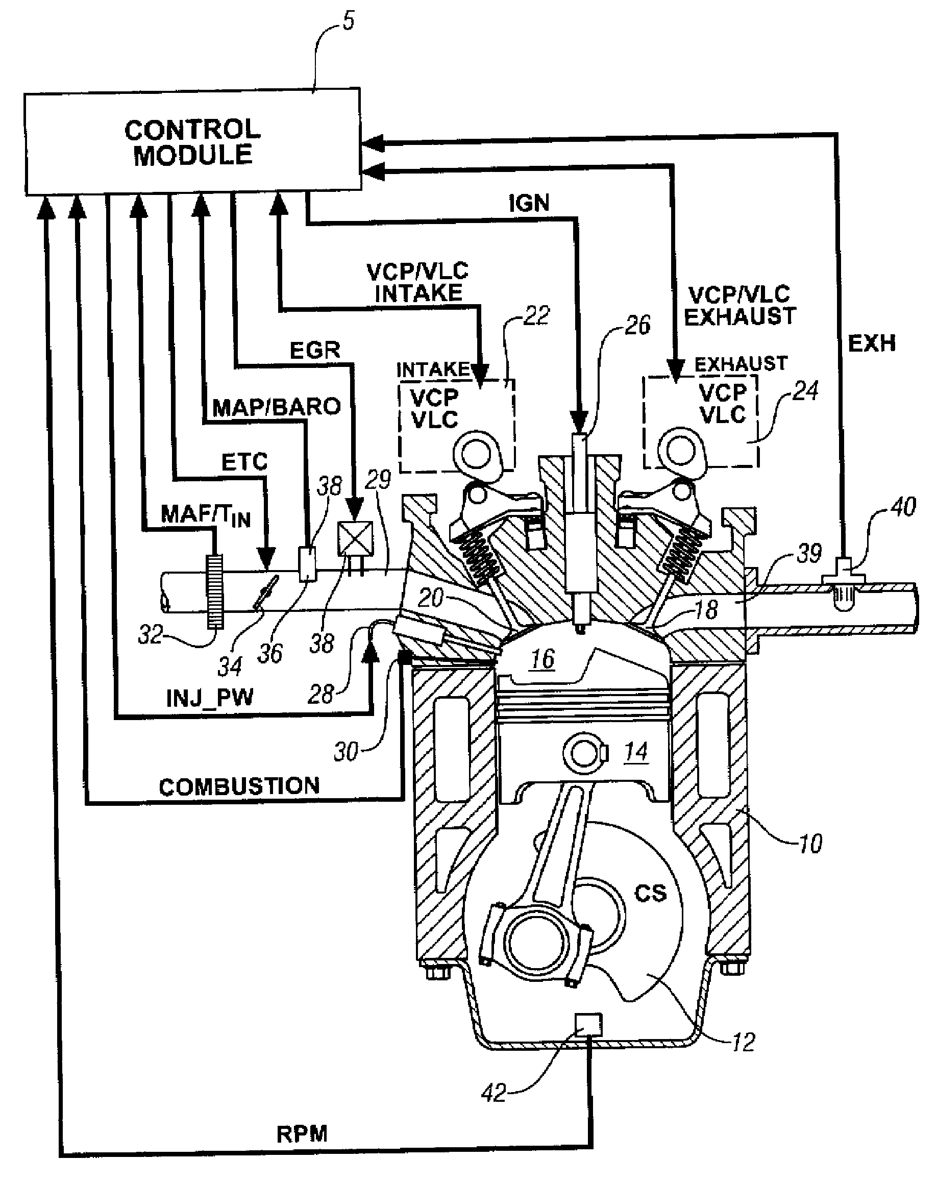
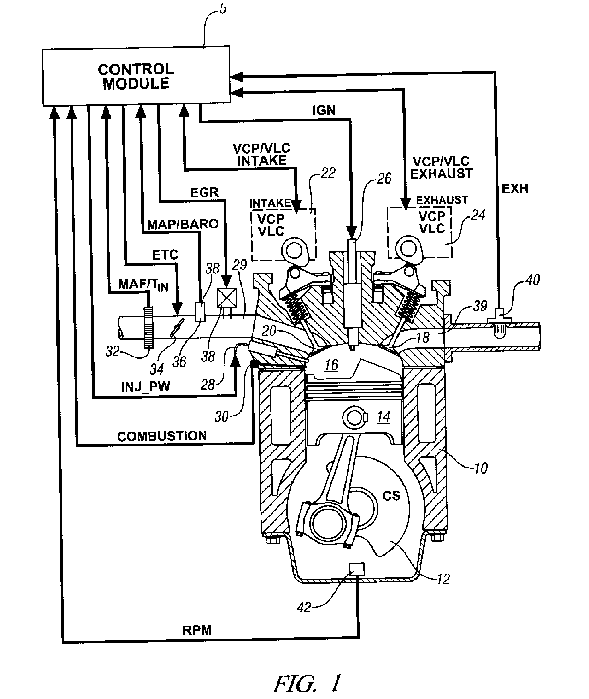
[0015]Referring now to the drawings, wherein the depictions are for the purpose of illustrating the invention only and not for the purpose of limiting the same, FIG. 1 depicts a schematic diagram of an internal combustion engine 10 and accompanying control module 5 that have been constructed in accordance with an embodiment of the invention. The engine is selectively operative in a controlled auto-ignition mode and a conventional spark-ignition mode.

[0016]The exemplary engine 10 comprises a multi-cylinder direct-injection four-stroke internal combustion engine having reciprocating pistons 14 slidably movable in cylinders which define variable volume combustion chambers 16. Each of the pistons is connected to a rotating crankshaft 12 (‘CS’) by which their linear reciprocating motion is translated to rotational motion. There is an air intake system which provides intake air to an intake manifold which directs and distributes the air into an intake runner 29 to each combustion chamber ...


PUM


Abstract

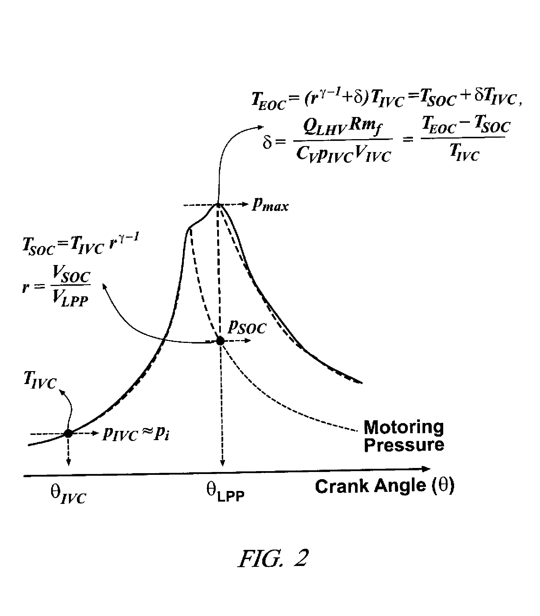
There is provided a method to determine a combustion parameter for an internal combustion engine. The method comprises monitoring cylinder pressure and crank angle during a combustion cycle, and determining a peak cylinder pressure, a crank angle location of the peak cylinder pressure, and a cylinder pressure at a closing of an intake valve. A combustion parameter is calculated based upon the peak cylinder pressure, the cylinder pressure at the closing of the intake valve for the combustion cycle, the crank angle location of the peak cylinder pressure, the cylinder volume at the location of the peak cylinder pressure, and the cylinder volume at the closing of the intake valve for the combustion cycle. The combustion parameter correlates to an instantaneous heat release of a cylinder charge for the combustion cycle.

Description

TECHNICAL FIELD[0001]This invention relates to operation and control of engines, including homogeneous-charge compression-ignition (HCCI) engines.BACKGROUND OF THE INVENTION[0002]The statements in this section merely provide background information related to the present disclosure and may not constitute prior art.[0003]Internal combustion engines, especially automotive internal combustion engines, generally fall into one of two categories, spark ignition engines and compression ignition engines. Traditional spark ignition engines, such as gasoline engines, typically function by introducing a fuel / air mixture into the combustion cylinders, which is then compressed in the compression stroke and ignited by a spark plug. Traditional compression ignition engines, such as diesel engines, typically function by introducing or injecting pressurized fuel into a combustion cylinder near top dead center (TDC) of the compression stroke, which ignites upon injection. Combustion for both tradition...

Claims


Application Information

Patent Timeline
Patent Type & Authority Applications(United States)
IPC IPC(8): F02D41/00
CPCF02D35/02F02D35/023F02D35/028F02D41/3035F02D41/3064
Inventor KANG, JUN-MO
Owner GM GLOBAL TECH OPERATIONS LLC
Learn More